
Soil moisture meter circuit

The soil moisture meter circuit is designed to measure the volumetric water content in soil, providing valuable data for plant care and irrigation management. The circuit typically consists of a moisture sensor, an operational amplifier, a microcontroller or analog meter for display, and a power supply.
The moisture sensor is usually a resistive type, where two electrodes are inserted into the soil. The resistance between the electrodes changes with the moisture content; drier soil has higher resistance, while wetter soil exhibits lower resistance. This change in resistance can be converted into a voltage signal using a voltage divider configuration.
The operational amplifier amplifies the voltage signal from the sensor, ensuring that it is within the appropriate range for the microcontroller or display device. If an analog meter is used, the output from the operational amplifier can be directly connected to the meter, providing a visual indication of soil moisture levels.
In more advanced designs, a microcontroller can be programmed to interpret the sensor data and control additional features, such as activating a pump for irrigation when moisture levels fall below a predefined threshold. The microcontroller can also provide a digital readout of the moisture level on an LCD or LED display, allowing for easy monitoring.
Power supply options for the circuit can include batteries or a DC power adapter, depending on the intended application and portability requirements. Proper calibration of the sensor is essential to ensure accurate readings, which may involve testing in soils of varying moisture content.
Overall, this soil moisture meter circuit is an essential tool for gardeners and farmers, helping to optimize water usage and promote healthy plant growth.Soil moisture meter circuit is usefull for monitoring the moisture at your plants. An easy circuit and very usefull.
Related Circuits
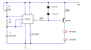
A TV remote jammer circuit using the NE555 timer IC. This device allows users to watch their favorite TV channels without interruptions, as it prevents others from changing the channel using a remote control when the circuit is activated....
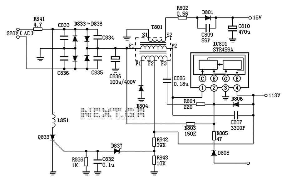
The Panasonic M12H switching power supply circuit is utilized in Panasonic models such as TC-230H, TC-2030DHN, TC-830D, and TC-840D. The circuit operates with an oscillation frequency that generates approximately 300V DC voltage at C836. The T801 transformer is involved...
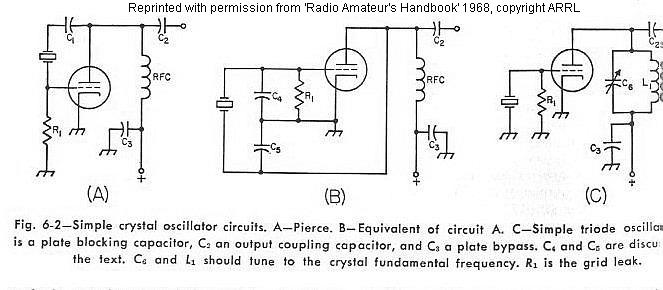
The frequency of a crystal-controlled oscillator is maintained with high precision through the use of a quartz crystal. The frequency is primarily determined by the dimensions of the crystal, particularly its thickness, while other circuit parameters have minimal impact....

The circuit comprises an infrared sensor control circuit, a relay control circuit, a music generating circuit, and additional components. It is applicable for use in infrared alarms, timing control, and various other applications. The circuit design integrates several functional modules...
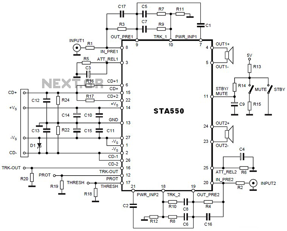
This is a 2 x 70W audio power amplifier circuit built using a single IC STA550. The amplifier circuit requires a few external components, primarily resistors and capacitors, and is straightforward to design. The STA550 audio amplifier can provide...

When the system is placed in a shop or mall, logos and product advertisements serve as an ideal complement to temperature information. For home use, photographs of children at the beach or, should the temperature drop, images of making...