
ir remote switch circuit

This circuit design employs a TRIAC (Triode for Alternating Current) as the primary switching element, allowing for the control of AC loads. The infrared receiver module is responsible for detecting the modulated signals emitted by the remote control. When an IR signal is received, the output of the receiver activates the gate of the TRIAC, allowing current to flow to the connected device.
The circuit's power supply is transformerless, which means it derives power directly from the AC mains. This is achieved through a capacitive dropper circuit that limits the current to a safe level for the control circuitry. The design must ensure that all components are rated for the line voltage to prevent damage or hazards.
The integration of this circuit within a housing, such as a light switch or power bar, requires careful consideration of heat dissipation, as the TRIAC may generate heat during operation. Adequate spacing and ventilation should be considered in the design to ensure reliable operation.
Additionally, the circuit can be enhanced with features such as a delay timer or dimming capability by incorporating additional components like microcontrollers or dimmer circuits. This would allow for more versatile control of the connected devices, catering to user preferences for lighting and other functionalities.
Overall, this circuit provides a practical and efficient solution for repurposing old IR remotes while offering a user-friendly interface for controlling various household appliances.This circuit lets you control any line powered electrical device (a lamp, television, fan, etc. ) using any infra-red remote control. Almost everyone these days has a pile of old IR remotes left over from appliances they have long ago disposed of them. With this circuit, you can put them back into use. The circuit looks for any modulated IR source and uses it to control a TRIAC, which then switches any appliance connected to it`s socket. For example, you can use it to control the room lighting in your home theater setup using any of the remotes you already have. The circuit is powered using a simple transformerless power supply from the line itself, making it compact and easily built into a light switch, wall box, power bar or even the appliance you wish to control.
🔗 External reference
Related Circuits
A project of a 555 tester circuit, the circuit will start blinking LEDs when power is applied, which will indicate that the IC is working correctly. The 555 tester circuit is designed to verify the operational status of the 555...
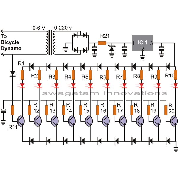
The article presents a circuit that can be used for indicating the riding speed of a bicycle. The bicycle speedometer circuit explained here utilizes standard components such as transistors and LEDs to effectively display a clear 10-step, accurately calibrated...
This circuit displays a sound generator that simulates the siren of a British police car. The circuit is constructed using two timer IC 555. The sound generator circuit designed to simulate a British police car siren utilizes two 555 timer...
This is a birthday heart circuit. No much description is available but you can use your experienced imagination! The birthday heart circuit is designed to create a visually appealing display, often used as a decorative element for celebrations. The circuit...

In some buildings, there is a need for effective security measures. An example of this is the door knock alarm, which is a simple design intended for basic home security. This circuit utilizes a piezoelectric sensor to detect knocking...
The circuit presented is a remote control unit that utilizes radio frequency signals to manage various electrical appliances. This remote control unit is designed with 4 channels but can be expanded to 12 channels. Its design is notable for...