
Birthday Heart circuit

The birthday heart circuit is designed to create a visually appealing display, often used as a decorative element for celebrations. The circuit typically utilizes a series of light-emitting diodes (LEDs) arranged in the shape of a heart to provide illumination. The heart shape can be created using a printed circuit board (PCB) or a simple breadboard setup, depending on the complexity desired.
Power for the circuit is usually supplied by a low-voltage source, such as a battery or USB power supply, ensuring safety and ease of use. A common choice for the power supply is a 5V source, which is compatible with most standard LEDs.
To control the LEDs, a microcontroller or a simple timer circuit can be employed. For example, a 555 timer IC can be configured in astable mode to create a blinking effect, enhancing the visual appeal of the heart circuit. Alternatively, a microcontroller such as an Arduino can be programmed to control the timing and patterns of the LED illumination, allowing for more complex light displays such as fading or chasing effects.
The circuit may also include resistors to limit the current flowing through the LEDs, preventing damage and ensuring longevity. The value of the resistors can be calculated based on the forward voltage and current specifications of the chosen LEDs.
For enhanced functionality, additional components such as a switch can be integrated to turn the circuit on and off, or a potentiometer can be included to adjust the brightness of the LEDs. This flexibility allows for customization based on user preferences.
Overall, the birthday heart circuit serves as an engaging and festive electronic project, combining basic electronic components with creative design to celebrate special occasions.This is a birthday heart circuit. No much description is available but you can use your expirienced imagination! ;) 🔗 External reference
Related Circuits
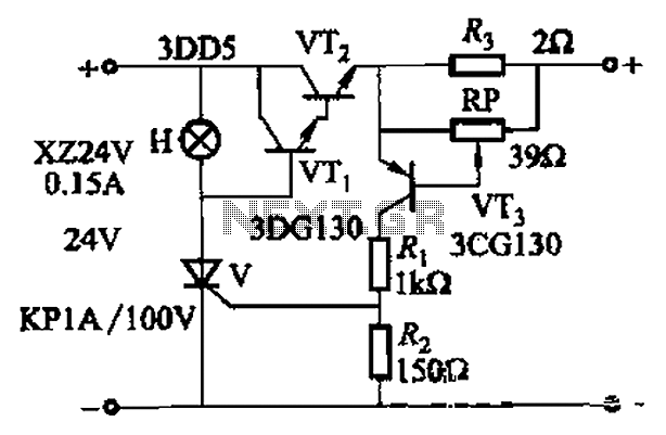
By adjusting Ro or RP, the current setpoint can be modified. The circuit illustrated in Figure 14-98 features overcurrent protection using a thyristor and transistors VTi and VT2, which immediately cut off the power when an overcurrent condition is...
This circuit provides a visual 9-second delay using 10 LEDs before closing a 12-volt relay. When the reset switch is closed, the 4017 decade counter is reset to the 0 count, illuminating the LED driven from pin 3. The...

This DC to DC converter increases a DC voltage to nearly double its original value and is useful for elevating the output voltage of solar batteries to the required level. The DC to DC converter operates on the principle of...
The TDA2030 is a monolithic integrated circuit in a Pentawat® package designed to function as a Class AB audio amplifier. It typically delivers up to 14 watts of output power (with a distortion rate of 0.5%) at 14V with...
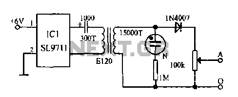
The electronic frostbite treatment instrument ASIC SL9711 consists of an oscillation circuit, a power amplifier, and a controller. It generates a sine wave at frequencies of 100 Hz and 3 Hz, followed by a step-up transformer with potentiometer adjustment...

The power supply circuits for servo systems are critical during both the adoption and operational stages. The power supply circuit for servo systems is designed to provide stable and adequate voltage and current levels necessary for the servo motors to...