
bicycle speed indicator circuit explained

The bicycle speedometer circuit operates on the principle of converting the mechanical rotation of the bicycle wheel into an electrical signal. The dynamo, typically mounted on the bicycle frame, generates an alternating current (AC) voltage as the wheel turns. This AC signal is then rectified using a diode bridge to convert it into direct current (DC), which is necessary for the subsequent processing.
The core of the circuit involves a microcontroller or a comparator circuit that interprets the varying voltage levels from the dynamo. By calibrating the circuit, it can map the voltage levels to specific speed ranges. For instance, the circuit can be designed to illuminate different LEDs corresponding to speed intervals, providing a visual indication of the bicycle's speed.
Transistors are used in this circuit as switches or amplifiers to control the LEDs. When the voltage reaches a certain threshold, the transistor activates, allowing current to flow to the corresponding LED. This arrangement can create a 10-step LED display, where each LED represents a specific speed range, enhancing the user’s ability to monitor speed at a glance.
To ensure accuracy, the circuit may include a feedback mechanism or a calibration feature that allows users to adjust the sensitivity based on tire size or other factors affecting speed measurement. Additionally, the design may incorporate a low-pass filter to smooth out any fluctuations in voltage readings, providing a more stable and reliable speed indication.
Overall, this bicycle speedometer circuit exemplifies a practical application of basic electronic components to create an effective speed measurement tool, enhancing the cycling experience through real-time feedback on performance.The article presents a circuit that can be used for indicating the riding speed of a bicycle. The circuit of a bicycle speedometer explained here uses ordinary components like transistors and LEDs and yet succeeds in displaying a distinct 10 step, accurately calibrated linear reading, corresponding to the instantaneous speed of the bicycle wheels. The source is basically derived from a dynamo that generates electricity levels directly proportional to the speed of the bicycles rotating wheel, this varying potential is translated by the circuit into the corresponding reading through the illuminated LEDs..
🔗 External reference
Related Circuits

Active speaker with amplifier circuit TDA1521 and NE5532, featuring dual-channel input and dual-channel output. The active speaker circuit utilizes the TDA1521 integrated circuit, which serves as the power amplifier. This IC is designed for high-efficiency amplification, providing a robust output suitable...

A simple photo switch circuit using an NE 555 IC with a diagram and schematic. This photo switch activates a relay when light intensity crosses a specified limit. It is a light sensor circuit suitable for home and industrial...

This circuit is designed to detect microwave sources, such as microwave ovens, satellite communication devices, and mobile phones. It provides audio-visual indications when microwaves in the gigahertz band are detected. Microwaves are a form of electromagnetic radiation with frequencies...
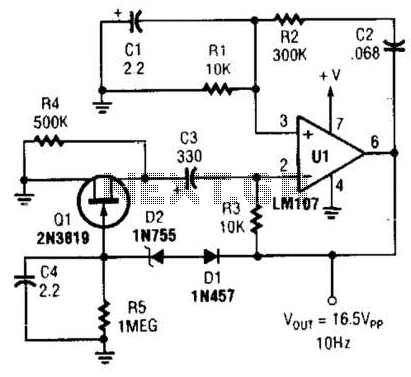
This Wien-bridge sine-wave oscillator utilizes a 2N3819 as an amplitude stabilizer. The 2N3819 functions as a variable-resistance element within the Wien bridge. The Wien-bridge oscillator is a type of electronic oscillator that generates sine waves. It employs a bridge circuit...

This circuit is designed to record telephone conversations on a landline telephone. It requires a small circuit and a computer subscription. Recording conversations is useful for recalling important discussions. Previously, this was accomplished using a small tape recorder, where...
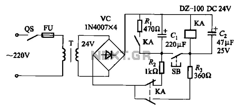
After the turn-off circuit is first applied to the next KA KA, the intermediate interval required is less than Is. This is due to the time needed, which is equal to three times the charge time constant of the...