
IR Short Distance Beam Cut Detector

The circuit operates effectively within its specified range, making it suitable for applications requiring precise light beam interruption detection. The design's simplicity facilitates easy integration into various projects, particularly where space and power constraints are present. The use of a potentiometer for sensitivity adjustment enhances its versatility, allowing it to cater to different detection requirements. Furthermore, the configuration minimizes potential interference from ambient light, ensuring reliable operation in practical scenarios. The compact nature of the circuit also allows for easy implementation in devices like rotary encoders, where space is often at a premium. Overall, this light beam detection circuit presents a practical solution for applications requiring short-range light interruption detection with minimal interference.A circuit that can detect a light beam cut. The first circuit i made was a light/dark detector with photoresistor. Although it could sense the light cut, it had a major disadvantage: extreme interferences from ambient light. That is why i designed this simple circuit. I tried to keep it as simple as possible. The maximum distance of the IR LED pair that i used is up to about 2. 5cm (close to 1 inch). That explains the title "Short Distance". It has a very good sensitivity. With a potentiometer you can adjust it to sense completely opaque objects, or it can sense semi-transparent films as well! It is also suitable for rotary encoders. It is not suitable for making security systems which require a beam that can go up to 3 or 4 meters long.
This is the first part of this IR pair. The transmitter circuit is a pulse generator that drives an infrared LED. I have use the good old 555 chip. The pulses are about 1. 5KHz. You can use of course any kind of pulse generator like an Astable Multivibrator transistor circuit. That is up to you. Here is the schematic for the 555 connected as an astable multivibrator, oscillating at around 1. 5KHz: I began designing a complicated interference-proof circuit, with an active filter and other stages of filtering. Then, i realized that i was going the long way. There is no need for such filtering. This is an IR pair that will be most likely inside a housing, with the transmitter close to the receiver, away from parasitic lights.
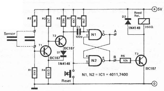
So, i start removing stages until i got down to minimum. The circuit that follows can be powered with a single 5 volts supply (unlike the other circuits that i designed that required double power supply). It has a simple capacitors filter that drops all constant and low frequency IR light sources such as the sun, the household lighting.
The IR detector itself will reject any other source of light beyond the IR, such as other LEDs and the sun. So, the only thing that will interfere with the receiver is sources of high frequency modulated IR light, such as the TV remote controls.
But i supposed that if you built a rotary encoder, you will not turn the TV remote control directly to the receiver LED do you I might re-make the complicated filtered version and upload another circuit. First of all, notice the IR Detector LED that is connected reverse! And that is how it should be! This receiver will reject all light sources except the infrared. Then, the capacitor C1 will only allow the modulated IR light to go through. Constant light sources such as the sun, or low frequency such as the household light will not be allowed to go through.
Remember that both the sun and the household lamps, except the visible light, they emit also infrared light. Next is the adjustable gain amplifier. The R3-R4 voltage divider biases the base of the transistor. The R5 will set the maximum gain, while the potentiometer R2 will adjust the current that flows to the base of the amplifier.
The amplified signal will charge the capacitor C2. This capacitor also will smooth the signal into a constant straight line. The final stage is the comparator. The R7-R8 voltage divider will set the voltage reference. The comparison of the voltage across the C2 and this reference voltage, will result into a HIGH or LOW output of the comparator. As long as the IR beam reaches the receiver LED1, the signal will be amplified (and inverted) from T1.
The C2 will then generate a voltage across its leads. This voltage level can be adjusted by R2. It must be less than the voltage of the non-inverting input (R7-R8 voltage divider). The output of the comparator will then be HIGH. When the beam is cut, the output of the amplifier (T1) will be 5 volts, and that will also be the voltage across the C2. The inverting input of the comparator will be higher than the no 🔗 External reference
Related Circuits
This humidity detector circuit diagram is straightforward and utilizes a limited number of components. It can be employed to activate electronic devices when the detector identifies a specific humidity level. The sensor is made from two copper pieces positioned...
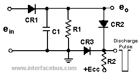
A peak detector is a circuit that detects the peak voltage of an incoming waveform. It is primarily used as an Amplitude Modulation (AM) detector, Pulse Amplitude Modulation (PAM) detector, or envelope detector. The basic form of a peak...
A gas leak detector circuit that detects the leakage of LPG gas and alerts the user through audio-visual indications. The circuit operates off a 9V PP3 battery. A Zener diode is used to convert 9V into 5V DC to...
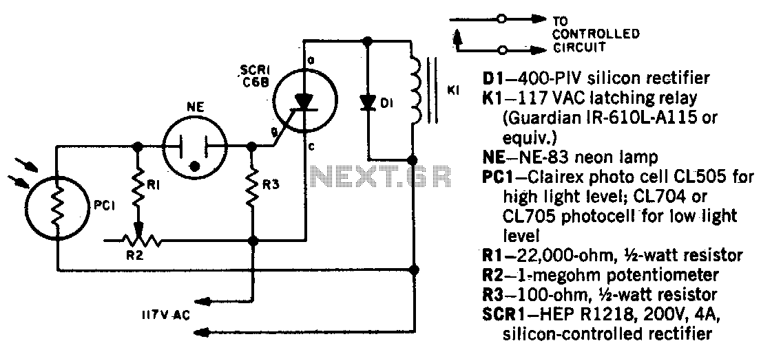
When a beam of light strikes the photocell, the voltage across the neon lamp NE-1 rises sharply. NE-1 turns on and triggers the SCR. K1 is an impulse relay whose contacts remain in position even after the coil current...
Metal detectors are usually very complicated and it may be consist of very costly components and metal detector DIY circuits are rare. However this metal detector hobby circuit can be constructed by only a few components such as BC548...

This circuit is the simplest inductive balancing metal detector (IB, Induction Balance) that can be constructed. The LB metal detection method offers satisfactory depth of penetration and effectively distinguishes between iron-based and noble metallic objects. While several metal detectors...