
Low cost Metal Detector

Working
We all need to adjust the frequency of electronics circuit of metal detector to the tuned radio frequency. Whenever a metal part come aside the circuit, the cancellation of two signals stops and the radio starts producing sound.
Important: Never assemble the circuit in a metal cabinet. Do the circuit on a common PCB and assemble in a plastic cabinet.
The described metal detector circuit utilizes a BC548 transistor, which is a general-purpose NPN transistor commonly used in various electronic applications. In this circuit, the BC548 serves as the primary active component that facilitates the oscillation process necessary for detecting metal objects.
The circuit operates by creating a feedback loop that generates oscillations at a frequency that corresponds to the tuning of an ordinary AM radio. The AM radio is used as a detection mechanism; when the metal detector is powered on, both the circuit and the radio will be tuned to the same frequency, resulting in a phenomenon known as signal cancellation. This means that no sound will be emitted from the radio when the circuit is in its idle state.
To configure the circuit correctly, it is crucial to adjust the frequency of the metal detector circuit so that it matches the tuned frequency of the AM radio. This adjustment is typically achieved through the use of variable resistors or capacitors in the circuit design, allowing for fine-tuning to achieve the desired resonance.
The operational principle relies on the interaction between the oscillating signals. When a metallic object is brought within the detection range of the circuit, it disrupts the cancellation effect. This disruption allows the oscillation from the metal detector circuit to become dominant, causing the AM radio to emit sound, indicating the presence of metal.
It is essential to follow safety and design guidelines when constructing the circuit. As noted, assembling the circuit in a metal cabinet is not advisable, as the metal enclosure could interfere with the oscillations and affect performance. Instead, a common printed circuit board (PCB) should be utilized, and the entire assembly should be housed in a plastic cabinet to prevent any unwanted interference and ensure optimal functionality.
Overall, this metal detector circuit represents a simple yet effective approach to metal detection, making it accessible for hobbyists and enthusiasts with basic electronic skills.Metal detectors are usually very complicated and it may be consist of very costly components and metal detector DIY circuits are rare. However this metal detector hobby circuit can be constructed by only a few components such as BC548 and an ordinary AM radio that we usually use.
This metal detector schematic shown in the figure oscillates according to the frequency of any tuned AM radio. When the circuit powers up, the radio will not produce any sound because the radio oscillatory and the the metal detector oscillator will be in the same frequency and each will cancel itself.
Working We all need to adjust the frequency of electronics circuit of metal detector to the tuned radio frequency. Whenever a metal part come aside the circuit, the cancellation of two signals stops and the radio starts producing sound.
Important: Never assemble the circuit in a metal cabinet. Do the circuit on a common PCB and assemble in a plastic cabinet. 🔗 External reference
Related Circuits
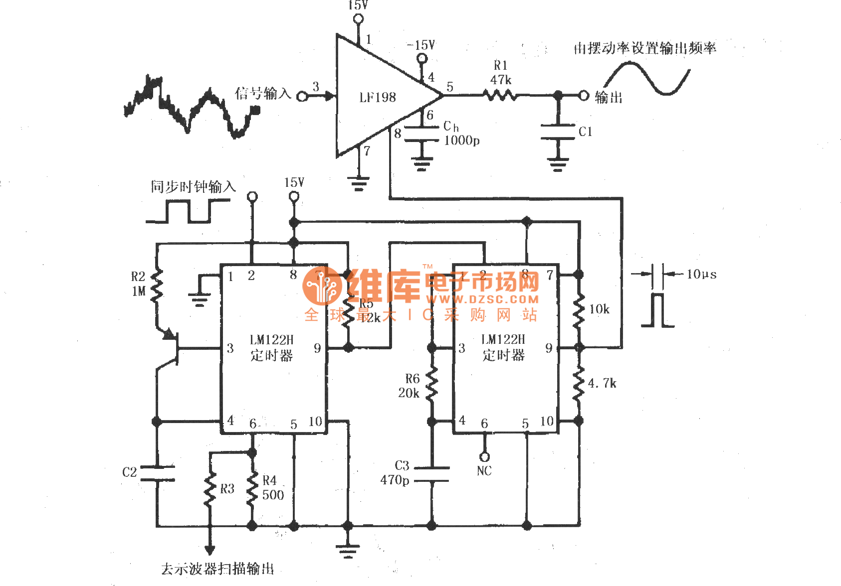
A synchronous clock signal is fed into a cascade of timer circuits composed of two LM122H devices. The synchronization clock is then converted into a pulse of the desired width, which is added to the LF198 logic end (pin...
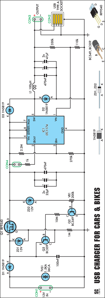
A regular charger was tested and found to consume 13mA with no load. It features an integrated power LED, which significantly contributes to standby current consumption. However, since the cigarette lighter socket is powered only when the engine is...
This circuit utilizes a 1458 dual op-amp to create a radar detector. C1 serves as the radar signal detector. The first op-amp functions as a current-to-voltage converter, while the second op-amp buffers the output to drive the piezo transducer....
This article addresses inquiries regarding a low-power FM transmitter designed to accept input from various sound sources, such as a guitar or microphone, and transmit on the commercial FM band. It is important to select an unused frequency on...
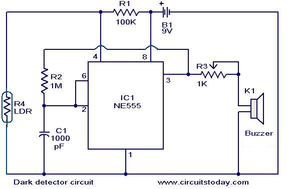
The dark detector circuit illustrated here is designed to generate an audible alarm when the ambient light in a room is turned OFF. The circuit is constructed around the timer IC NE555. A general-purpose light-dependent resistor (LDR) is utilized...

To achieve optimal performance as a low noise, high input impedance device, the preamplifier and tone control utilize JFET technology. The circuit is designed to minimize harmonic distortion levels. The use of Junction Field Effect Transistors (JFETs) in the preamplifier...