
Isolated Telephone Interface

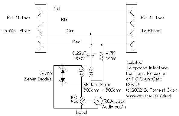
Note that some countries have laws that require the user of a phone recording device to notify the party on the other end of the line that they are being recorded. More: There’s not much to this circuit. The two RJ-11 jacks are set up to feed the telephone circuit through from the wall to the phone. The active signal for a single phone is on the red and green wires. Yellow and black are usually used for a second phone.
This circuit is designed to facilitate audio recording from a telephone line. It employs two RJ-11 jacks, which are standard connectors used in telephone wiring. The first RJ-11 jack connects to the telephone line from the wall, while the second jack connects to the telephone device itself. This configuration allows for the seamless passage of the telephone signal without disrupting normal phone operation.
The active audio signals are transmitted through the red and green wires, which are designated for the primary phone line. The yellow and black wires typically serve as the secondary line in a multi-line setup, but in this circuit, they may not be utilized unless a second phone is connected.
To implement this circuit, a basic understanding of audio recording and telephone line characteristics is beneficial. The circuit may require additional components such as capacitors or resistors to filter the audio signal and ensure compatibility with recording devices, whether they are tape recorders or computer sound cards.
When assembling the circuit, it is critical to ensure that the recording device is capable of handling the audio levels from the telephone line to avoid distortion or damage. Additionally, it is advisable to incorporate a switch that allows the user to select between recording and normal phone operation, thus preventing accidental recordings.
Care should also be taken to comply with local laws regarding telephone recording, which often require notifying participants that the conversation is being recorded. This circuit, while simple, provides an effective means of capturing audio from telephone communications for various applications, including documentation and analysis.This circuit allows you to record audio from a telephone line into a tape recorder or computer soundcard. Most of the parts for this circuit can be scrounged from an old modem, with some work, it is possible to rewire the modem circuitry and use the old modem case.
Note that some countries have laws that require the user of a phone recording device to notify the party on the other end of the line that they are being recorded. There`s not much to this circuit. The two RJ-11 jacks are set up to feed the telephone circuit through from the wall to the phone. The active signal for a single phone is on the red and green wires. Yellow and black are usually used for a second phon 🔗 External reference
Related Circuits
There's not much to this circuit. The two RJ-11 jacks are set up to feed the telephone circuit through from the wall to the phone. The active signal for a single phone is on the red and green wires....
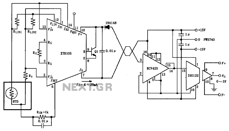
The RTD temperature sensor, as illustrated in the subsequent figure, collects temperature data from the field. This data is converted into a voltage signal by the XTR105, which is then transformed into a 4 to 20 mA current output....
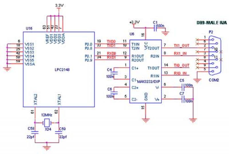
The interfacing of a Bluetooth module with the LPC2148 microcontroller is a straightforward process that enables the transmission of messages from the LPC2148 Primer Board to mobile devices via Bluetooth using UART0. Some delays may occur when sending a...
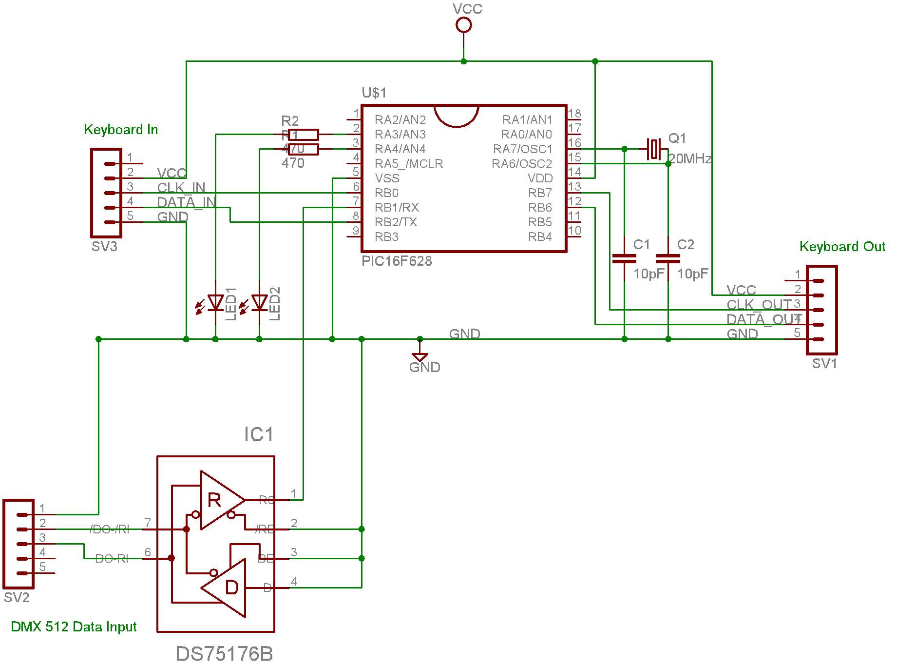
This system is designed for use with a PC connected to video projectors, enabling a lighting controller to manage a presentation displayed on the video screen. The PC used for the presentation is situated in a different location from...
Here is an inexpensive way to get slow-moving analog data directly into a spreadsheet on your computer! A simple circuit connects to a serial port and a short Qbasic program gathers and saves 12 bit data to a file....
A telephone ringer capable of making any mains-powered device operate from the ringer of a fixed line telephone. This device allows the control of a high-powered siren or horn to amplify the low-level sound of a telephone, making it...