
8 Pin PIC12C508A and PIC16F84 programmer circuit

The circuit designed for programming the PIC12c508A and PIC16F84 microcontrollers utilizes a standard IC programming approach, which allows for flexibility in programming various microcontrollers within the specified pin configurations. The programming interface typically includes a series of connections that link the programmer to the target microcontroller, ensuring proper communication and power supply during the programming process.
Key components of the circuit include a microcontroller programmer, which serves as the central unit for controlling the programming sequence. The programmer interfaces with a host computer via USB or serial communication, allowing the user to upload firmware or configuration files. The programmer’s firmware must be compatible with the IC-Prog software, which provides a user-friendly interface for selecting the target microcontroller and managing the programming operations.
The circuit also incorporates level shifters or voltage regulators to ensure that the programming voltage levels are compatible with the target microcontrollers, as different microcontrollers may operate at different voltage levels. For instance, the PIC12c508A typically operates at 5V, while some other microcontrollers might require lower voltage levels, necessitating the use of appropriate voltage conversion components.
Additionally, the schematic will include necessary connections for programming pins such as MCLR (Master Clear), PGD (Program Data), and PGC (Program Clock). These pins are essential for the programming process, allowing the programmer to send and receive data from the microcontroller. Pull-up resistors may be included on the MCLR pin to ensure proper reset behavior during programming.
To enhance reliability, decoupling capacitors should be placed near the power supply pins of the microcontroller to filter out noise and stabilize the supply voltage during operation. The layout should also consider trace lengths and widths to minimize inductance and resistance, which can affect the programming signal integrity.
In conclusion, this programming circuit is designed to be versatile and efficient, supporting various 8-pin and 18-pin microcontrollers while ensuring adherence to the specifications required for successful programming. The use of established programming protocols and careful circuit design will result in a robust solution for microcontroller programming needs.This project is designed to program the 8-pin PIC12c508A and 18pin PIC16F84 microcontroller chips to support the projects we have designed, however it will also program a number of other 8-pin & 18-pin microcontrollers and the full list can be seen when using IC-Prog. 🔗 External reference
Related Circuits
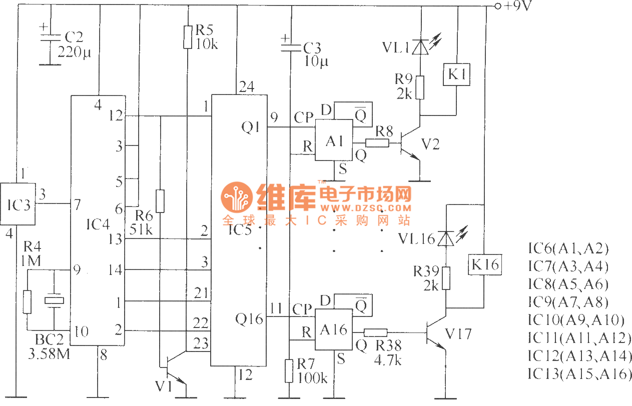
The wireless remote control transmitter circuit consists of control buttons S1 to S16, resistors R1 to R3, a capacitor C1, a regulator diode VS, a crystal oscillator BC1, and DTMF encoder integrated circuits IC1 and IC2. The circuit components...
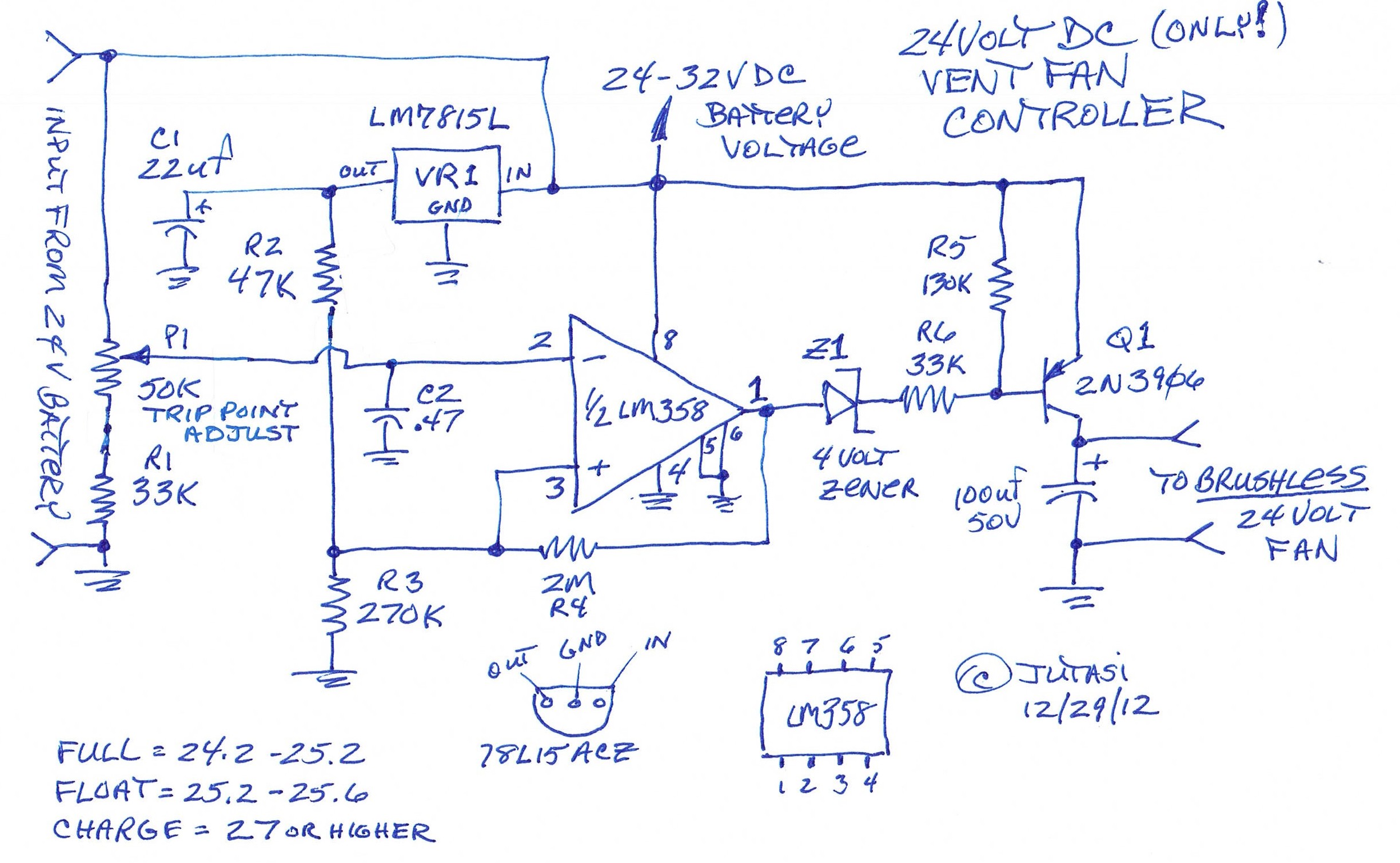
One of the backup systems utilizes a Magnum MS-PAE 4024 inverter, which lacks a built-in fan controller. Since batteries emit hydrogen during both normal and equalization charging, it is crucial to ventilate the batteries to the outside using a...
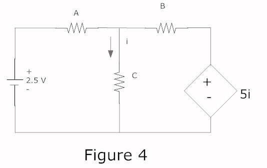
In a complete circuit, there are two types of elements: active and passive elements. Active elements generate energy, while passive elements dissipate energy. Examples of passive elements include resistors and capacitors. In electronic circuits, active and passive components serve distinct...
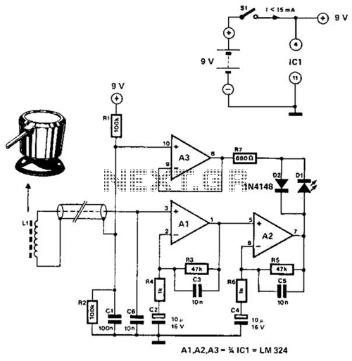
The circuit utilizes the principle that in an RL circuit, the pulse width across the inductor is proportional to the inductance. This circuit indirectly measures the inductance using a digital voltmeter (DVM). The measurement range is approximately 5 to...

Instructions for using an LED-Wiz to control pinball solenoids. Rottendog Amusements manufactures modern replacement driver boards, such as the Williams WPC89/WPC-S replacement. Although this board is an improvement over the originals, it remains relatively large and is capable of...
The circuit operates by monitoring the water level in a tank. When the water level falls below a specified point (F), the RS flip-flop (F2) is activated, producing a high Q output that energizes a relay to start the...