
It ZD1 type forklift battery control circuit

The circuit involves a cam controller designated as SA 1, which is responsible for managing the operation of two motors: M1, a driving motor rated at 1.35 kW, and M2, a pump motor rated at 4 kW. The contact closure case indicates that the controller utilizes a mechanical switch or relay system to initiate or terminate the operation of these motors based on the position of the cam.
The cam controller operates by detecting the position of the cam mechanism, which is typically linked to the operational cycle of the machinery. When the cam reaches a certain position, it causes the contact closure to occur, sending a signal to activate M1 or M2. The driving motor (M1) is primarily responsible for powering the mechanical components of the system, while the pump motor (M2) facilitates fluid movement, essential for the overall operation.
The control circuit may include additional components such as fuses for overload protection, contactors for motor control, and potentially a feedback loop to monitor the performance of the motors. The design must ensure that the current ratings and voltage levels are suitable for the motors in use, and that the contact closure mechanism is reliable to prevent unintended motor activation.
In summary, the schematic for this circuit will consist of the cam controller, relay contacts for M1 and M2, protection devices, and the necessary wiring to connect the motors to the power supply. Proper grounding and safety measures should also be incorporated to ensure safe operation within the designated parameters.Denote cam controller SA 1 contact closure case. M1 is 1. 35kW driving motor, Mz to 4kW pump motor.
Related Circuits
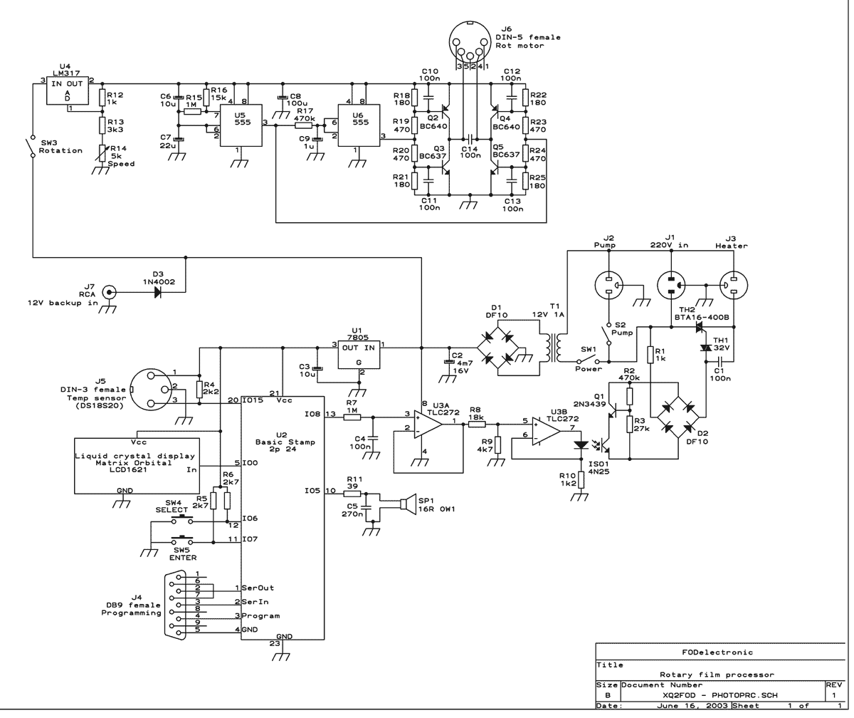
This machine essentially does three things: It controls the process temperature, provides constant agitation of the chemical baths, and performs the timing. The operator must pour in and out the liquids by hand. The heart of the circuit is...
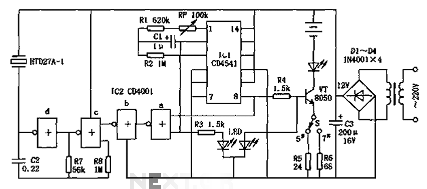
The CD4001/CD4541 nickel-cadmium battery automatic charger circuit is illustrated in the figure. This circuit is designed for charging up to seven rechargeable nickel-cadmium batteries. It features automatic charging with constant current characteristics. Once powered, the circuit activates an internal...
To achieve greater sensitivity, consider using the 74AC04 or 74HC04 in place of the 74HCU04 for component U1. While the 74AC04 and 74HC04 may offer improved performance over the 74HCU04, it is important to note that the frequency response...
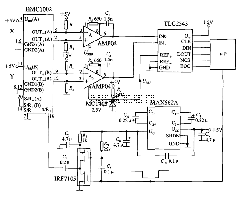
An application circuit for a biaxial magnetic field sensor is presented. This circuit utilizes the HMC1002 biaxial magnetic sensor along with two AMP04 amplifiers (A1, A2) to simultaneously measure magnetic fields in both the X-axis and Y-axis directions. The...
The schematic in question is unconventional in design and should not be used as a model for beginners in electronics. A significant drawback of this basic circuit is that the alarm is triggered only when the light beam on...
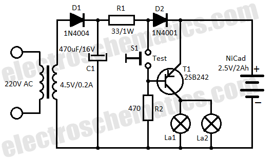
This low-cost automatic emergency lighting circuit activates a lamp during power failures. It is powered by a NiCad battery that is charged by the mains. The automatic emergency lighting circuit is designed to provide illumination during unexpected power outages. The...