
CD4541 circuit diagram of Ni-Cd battery is automatically charged

The CD4001/CD4541 charger circuit operates by utilizing a combination of digital logic and analog control to effectively manage the charging process for nickel-cadmium batteries. The circuit employs the CD4001 NAND gate IC and the CD4541 binary counter to provide a reliable method for automatic battery charging.
The charging sequence begins when the circuit is powered on. The internal oscillator within the CD4541 initiates a counting process, which is crucial for determining the charging duration. The counter increments until it reaches a predefined threshold, which corresponds to the maximum charge time needed for the batteries. Once this threshold is reached, the output at pin 8 of the CD4541 changes state. This output is used to control the charging current, ensuring that the batteries are charged safely and efficiently.
The design incorporates feedback mechanisms to monitor the charging process. The transition of the output at pin 8 serves as a trigger for the charging current to be cut off, preventing overcharging, which is a common issue with nickel-cadmium batteries. The circuit then resets, allowing the counting process to commence again, thus ensuring continuous operation without manual intervention.
This automatic charger circuit is particularly useful in applications where multiple nickel-cadmium batteries are used, as it simplifies the charging process and enhances battery life through careful management of the charging cycle. The use of standard ICs like the CD4001 and CD4541 makes this circuit both cost-effective and easy to implement in various electronic projects. As shown in Figure is CD4001/CD4541 nickel-cadmium battery automatic charger circuit. This circuit is designed for the 5th, on the 7th rechargeable nickel-cadmium batteries are designed with automatic charging, constant current charging characteristics. Circuit is shown. After power circuit starts to work, the internal oscillator counter counts until the count after the expiration, IC1 8-pin output level is inverted and stops counting. Such as the 10 foot M termination high, after the expiration of the 8-pin flip, then count, then flipped over so the cycle.
Related Circuits
At low output power, up to 18 W, the device functions as a standard BTL amplifier. When a greater output voltage swing is necessary, the internal supply voltage is increased using external electrolytic capacitors. This momentarily elevated supply voltage...

This is a simple passive headphone distribution box that functions effectively. It has been utilized in various recording studios and constructed for multiple users. The absence of active components ensures minimal failure risk and a quick assembly process. The...
High Power Siren Circuit. This article discusses a robust siren circuit suitable for various applications. A complementary transistor pair (BC557 & BC337) is configured as an oscillator to directly drive the speaker. Transistor Q1 (BC557) is utilized to ensure...
A DC capacitor tester circuit diagram utilizing a 555 timer is presented. The tester includes a pulse generator, a one-shot circuit, a DC amplifier, and a meter indication circuit. It is capable of measuring capacitors ranging from nanofarads (nF)...
The figure illustrates a schematic circuit of a UV sensor. When voltage is applied between the cathode and anode, and UV radiation passes through the quartz glass tube on the cathode's optical surface, the cathode material, which is coated...
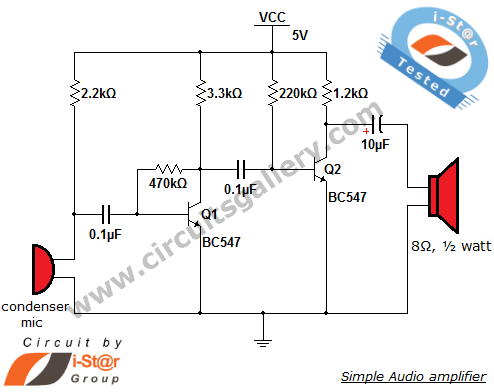
This circuit diagram is a simple and effective design for amplifying weak signals from a capacitive condenser microphone. It is suitable for sound sensing applications and various automatic robotic sensors. While a more complex audio amplifier circuit using the...