
pcb Need help with identifying diodes in a 1970s automotive circuit

The ignition module circuit from the 1978 W116 Mercedes-Benz serves as a crucial component in the vehicle's ignition system, responsible for controlling the timing and delivery of electrical pulses to the ignition coil. The reverse engineering process involves meticulous analysis of the PCB layout, component placement, and interconnections to reconstruct the original circuit functionality.
The identified components include various resistors, capacitors, and transistors, each playing a specific role in the operation of the ignition module. The transistors, specifically the BCY58IX series, act as switches that regulate current flow through the ignition coil, while the BSV15-16K transistor is likely used for voltage regulation or as a driver for higher currents.
The challenge lies primarily with the diodes, particularly ZD4 and ZD5, which are suspected to have high voltage ratings. These diodes may serve as voltage clamping devices or protection components within the circuit. The failure of diodes D3, D5, and D6 indicates potential over-voltage or reverse polarity conditions that could have led to their damage, suggesting that careful consideration should be given to the voltage levels applied during testing.
The identification of the missing T5 transistor, marked "1120008" and "7/32," is critical, as it likely influences the overall performance and reliability of the ignition module. The suggested BU426A replacement indicates compatibility, but verification of electrical characteristics such as current handling and switching speed is essential before substitution.
Overall, this reverse engineering effort aims to restore functionality to the ignition module by accurately mapping out the circuit and identifying suitable replacement components. The detailed understanding of the component functions and their interrelations will aid in troubleshooting and enhancing the performance of the ignition system in the vintage Mercedes-Benz vehicle.An old ignition module from a 1978 W116 model Mercedes-Benz, and I`m trying to "reverse engineer" it. The original circuit diagram is not available to mere mortals, so I have made one based on the PCB itself.
I believe it is, beside being ugly, electrically correct. Thus far I have identified all resistors, caps and transistors (bar one). What I have a huge problem with are the diodes, and any help would be appreciated. ZD4, ZD5, D1 to D8 are unknown. ZD4/ZD5 are not shorted, but I`m getting nowhere with these with my 30V power supply, so they`re probably rated above >30V. D3, D5 and D6 are fried. D4 is just beside R4. The two left-most black diodes are D1 and D8 (both marked "703"), the one underneath them is D7 (marked "1849" and "714").
The missing T5 transistor is a TO3 packaged power transistor marked "1120008" and "7/32". I haven`t cracked this one myself, but have been told a BU426A is a direct replacement for it. T1 to T3 are BCY58IX, T4 is a BSV15-16K. 🔗 External reference
Related Circuits
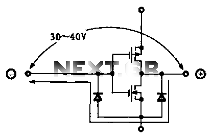
Due to the varying conditions of different input signals, when an abnormal voltage is applied to the pin, protection circuits are designed to create a circuit path that secures the internal protection of large-scale integration (LSI) circuits. The structure...
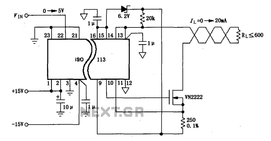
The circuit depicted in the figure consists of an ISO113 current loop isolation drive circuit that operates with an input signal (VIN) to provide an isolated amplified output of 0 to 20 mA. This current is transmitted to the...
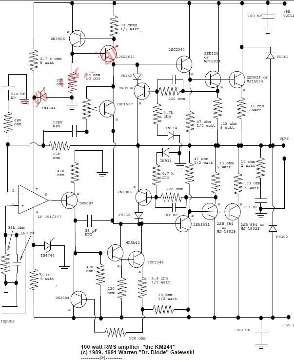
This is a 100-watt basic power amplifier designed to be relatively easy to build at a reasonable cost. It offers better performance, or musical quality, than the standard STK module amplifiers commonly found in mass-market stereo receivers. The design...
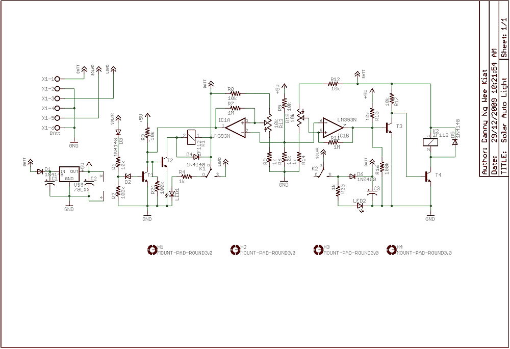
Few years back, I had been working on a project for solar auto lighting. The light will turn on when the solar panel voltage drop below a set point indicating that it is dark. The detection is done by...
This infrared transmitter utilizes pulse width modulation (PWM). The transmitter is equipped with an LM567 tone decoder circuit. An audio signal (at least 50 mV peak-to-peak) is amplified with transistor T1 and subsequently used to modulate IC1. The frequency...
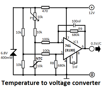
This simple temperature-to-voltage converter circuit allows for precise measurement of room temperature using an NTC resistor or thermistor. The temperature-to-voltage converter circuit typically employs a negative temperature coefficient (NTC) thermistor, which exhibits a decrease in resistance as temperature increases. This...