
joule savercircuit

The circuit design incorporates a joule saver mechanism aimed at enhancing the operational efficiency of the LED lighting system. The primary component, a capacitor, serves as an energy storage element that captures excess energy generated while the handle is being turned. This stored energy can then be released to power the LED light, ensuring it remains illuminated for a brief period after the handle stops turning.
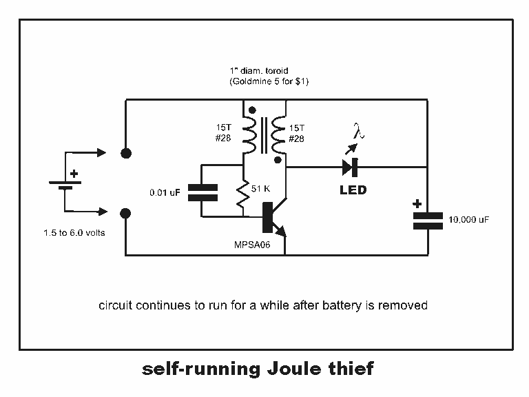
In this configuration, the capacitor is connected in parallel with the LED. When the handle is turned, the dynamo generates electrical energy, which charges the capacitor. The charging process continues until the handle is released, at which point the capacitor discharges its stored energy to the LED. This results in a sustained light output, providing a visual indication even after the mechanical input has ceased.
To optimize performance, it is essential to select a capacitor with an appropriate capacitance value, taking into account the LED's voltage and current requirements. Additionally, a diode may be included in the circuit to prevent backflow of current, ensuring that the capacitor only discharges to the LED and not back to the power source.
The overall schematic should include the dynamo, a switch (if necessary), the capacitor, the LED, and the diode, clearly indicating the connections and polarity where applicable. This design not only improves user experience by extending the LED's illumination time but also contributes to energy efficiency by utilizing stored energy effectively.Already early in the process regarding the electronics we thought it could be useful to implement a joule saverin thecircuit. The intention using a joule saver is to keep the LED light even after stopping turning the handle. Therefore we chosen to incorporate a capacitor in the circuit. 🔗 External reference
Related Circuits

A 14-watt equivalent light operates with only 1.2 watts of input. The brightness of the light increases as it approaches the watt rating of the CFL bulb. This circuit can power the CFL at low or high voltages. A...
The title contains numerous words because this instructable integrates various concepts from multiple sources. The primary idea originated from Robomaniac's Desktop Energy Seed Lamp, combined with Witch's Growing Plants with LED Lights instructable and various wick gardening planters. The...
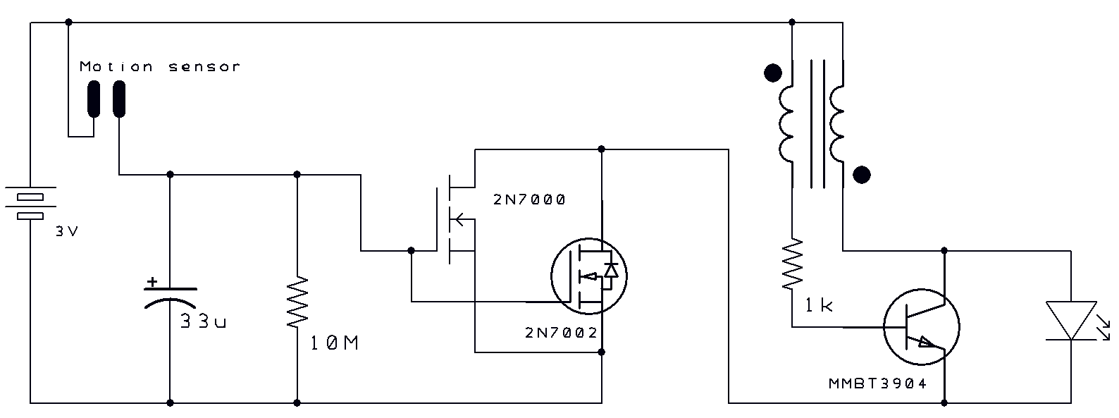
Two thoughts on a motion-activated Joule Thief LED bike light. The circuit for switching on and delayed switch-off is simple. The motion-activated Joule Thief LED bike light utilizes a straightforward circuit design that capitalizes on the principles of energy conservation...
It is essential to draw a circuit using a layout and conventions that are universally recognized. In electronic circuit design, adherence to standardized symbols and layout conventions is crucial for effective communication among engineers and technicians. A well-drawn schematic diagram...
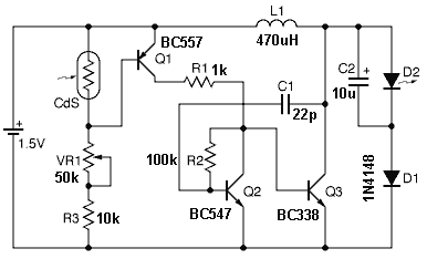
D1 (Schottky diode) and C2 form a rectifier to create DC voltage from the Joule Thief. A Zener diode D2 is included to limit the voltage to 5.1V, preventing damage to the microcontroller, which has a maximum voltage tolerance...
Professor Steven E. Jones' circuit demonstrates an 8x overunity. The concept of overunity refers to a system that produces more energy than is consumed, effectively achieving a coefficient of performance greater than one. In the context of Professor Steven E....