
Larson Scanner with Joule Thief Circuit

The described circuit utilizes several key components that work in concert to manage power efficiently and control LED behavior effectively. The Schottky diode D1 is chosen for its low forward voltage drop, which enhances the efficiency of the rectification process, ensuring that the maximum amount of energy from the Joule Thief is converted into usable DC voltage. Capacitor C2 plays a crucial role in stabilizing the voltage output, providing a reservoir of charge that allows the microcontroller to function reliably even during brief interruptions in power supply.
The Zener diode D2 is strategically placed to protect the microcontroller from overvoltage conditions, which could arise from fluctuations in the output of the boost converter. By clamping the voltage to a safe level, it ensures the longevity and reliability of the microcontroller, which is essential for the overall operation of the circuit.
The microcontroller's ability to monitor its own supply voltage and adjust the output accordingly is a critical feature that enhances the efficiency of the design. By keeping the voltage just below the Zener threshold, the circuit minimizes unnecessary power dissipation, thereby extending battery life.
The dual functionality of the PWR pin is an innovative design choice that maximizes the utility of the microcontroller's limited I/O resources. This arrangement not only simplifies the circuit but also allows for more complex interactions with the button switch, enabling user inputs to influence LED patterns and brightness dynamically.
The PWM control of the LED brightness is particularly noteworthy, as it employs an exponential scaling method that aligns with human visual perception. This approach results in a more natural and visually appealing transition of brightness levels, enhancing the overall user experience.
In summary, the circuit effectively integrates power management, user interaction, and LED control, demonstrating a sophisticated understanding of electronic design principles that prioritize efficiency and user engagement.D1 (Schottky diode) and C2 form a rectifier to create DC voltage out of the Joule Thief. Zener diode D2 is added to "clamp" or limit the voltage at 5. 1V to prevent damaging the microcontroller (maximum voltage this chip can withstand is 6V). Without the Zener diode there, the output voltage from the boost circuit can go over 6V when no LEDs are li
t. When the battery is first connected, the voltage charges the capacitor C2, then nothing happens until SW1 is closed. Once the SW1 is closed, current goes through R1 to turn on Q2, and the Joule Thief circuit starts working.
In afraction of a second, the voltage at C2 reaches high enough for the microcontroller to start up. Once the microcontroller starts running, it puts PWR signal high, so that the Joule Thief will keep running even after SW1 is open. (Power-on latch) Note that after initial power up, microcontroller watches its own supply voltage via A/D converter and adjusts it slightly below the zener voltage, so to not waste precious power from the battery.
"PWR" connection to the microprocessor does this by turning on/off bias current to Q2. This "PWR" pin has two purpose; one is to control the booster circuit, the other is to read the status of the button switch. (this arrangement saves a precious microcontroller pin. ) The button switch SW1 is more than a power switch, it provides pattern change, animation speed change (double tap to increase the speed, triple tap to decrease the speed).
Microcontroller reads the button state by periodically turning the "PWR" pin into an input pin. This happens roughly every 8 milliseconds (125 times/second). The reading of the button takes about 2 microseconds each. The booster circuit turns off during this 2 microseconds, but it won`t be felt because capacitor C2 supplies the power during that period.
Each of eight LEDs can have its own brightness level. Brightness is specified (in firmware) in 8 bit number 0 - 255. Timer interrupt routine reads the brightness levels and turn on/off each LED accordingly, in sync with the hardware PWM signal. (PWM frequency is 31. 25kHz. Interrupt occurs every 32 microseconds with firmware version 1. 0) Brightness change is very smooth - using the same PWM technique as my Aurora projects. Unlike other PWM implementations, the curve of brightness change is not linear, but exponent (anti-logarithmic).
This is important because our eye`s response to brightness change is more or less logarithmic, therefore LEDs need to change brightness in the opposite fashion. With Wave JT, the hardware PWM output is used as a precision clock to drive the LED bus (common line that connects to all LEDs) and "COLx" pins select which pulse to turn on the LED that`s connected to.
🔗 External reference
Related Circuits
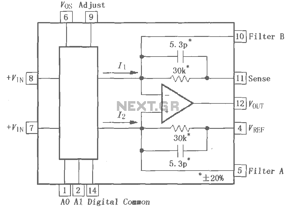
The PGA202 is a digitally controlled programmable gain amplifier with gain settings of G = 1, 10, 100, and 1000. The PGA203 offers gain settings of G = 1, 2, 4, and 8. Both amplifiers are compatible with CMOS...
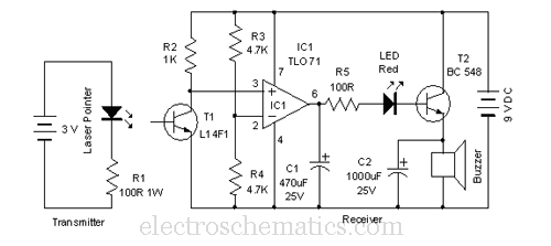
This laser door alarm operates by detecting the interruption of a laser beam. A low-cost laser pointer serves as the light source. When an individual crosses the path of the laser beam, it triggers the alarm. The laser door alarm...
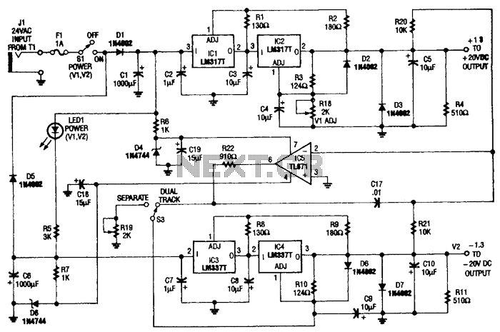
This circuit is useful for a bench supply in the lab. Separate or tracking operation is possible. The regulators should be properly heatsinked. Tl is a 24-Vac wall transformer of suitable current capacity. The described circuit functions as a laboratory...
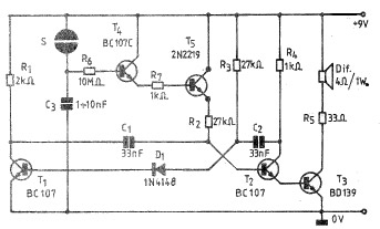
A simple and practical electronic bell circuit can be constructed using the provided schematic diagram. This circuit can function as a doorbell or an alarm system. It utilizes only a few transistors along with several common components. The circuit...
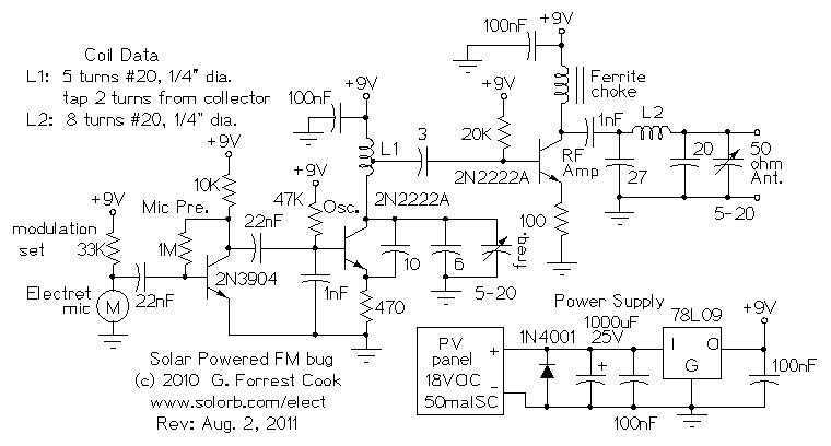
Here are some utility circuits for use with the Ramsey FM10a, and other small FM stereo transmitter kits. This information may be helpful for setting up a micro powered FM radio station. The FM10a and similar kits tend to...
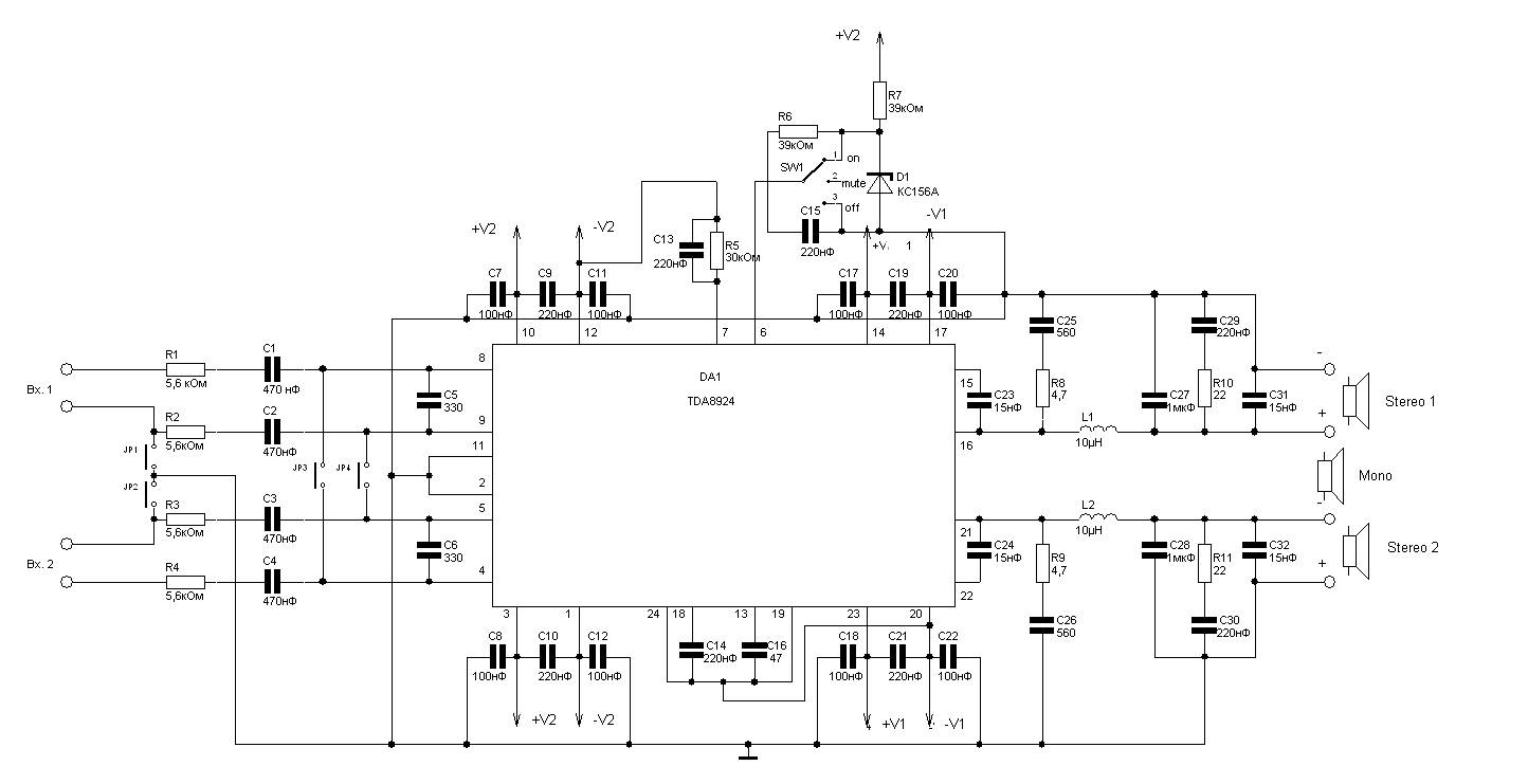
240W power amplifier circuit based on the TDA8924 class D design. This integrated circuit features short-circuit protection at the output, thermal protection, and safeguards against acoustic damage from inrush currents during power on and off. The schematic allows for...