
Joule Thief

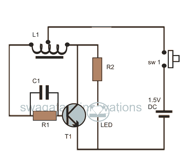
The circuit operates as a simple oscillator, utilizing the 2N4401 transistor to amplify the voltage generated by the hand-wound coil. The coil, with its center tap, allows for a feedback mechanism that sustains oscillation. When the circuit is powered by the depleted AAA battery, the low voltage is insufficient to directly drive the LED. However, the oscillation produced by the coil and transistor setup creates voltage spikes that exceed the forward voltage threshold of the LED, enabling it to emit light.
The choice of a 1k resistor is critical in this configuration, as it limits the current flowing through the transistor and protects the LED from excessive current that could cause damage. The hand-wound coil's design, with a specific number of turns and the use of solid core wire, directly influences the inductance and the efficiency of the oscillation. The use of a center-tapped coil is particularly advantageous, as it allows for a balanced feedback loop that stabilizes the oscillation frequency.
To enhance the circuit's performance, using smaller gauge wire will reduce the resistance of the coil, allowing for more efficient energy transfer. Increasing the number of turns on the coil will also improve the inductance, resulting in higher voltage spikes and a brighter LED output. The proposed rewiring with 38 gauge wire will enable a more compact coil design while maximizing the number of turns, further optimizing the circuit's functionality.
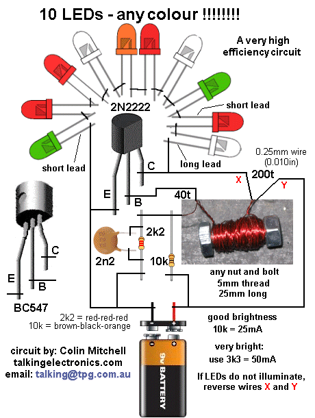
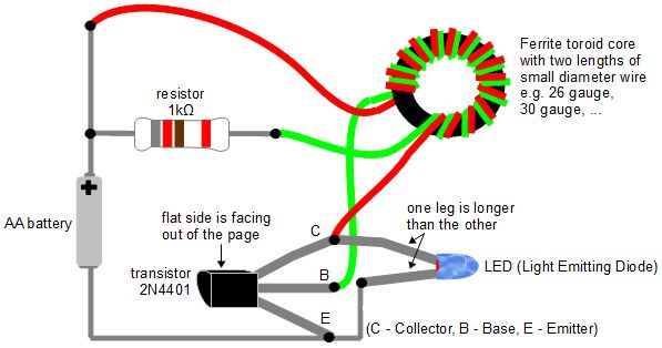
This circuit exemplifies a practical application of basic electronic components to create a functional light source from otherwise unusable batteries, showcasing innovation in circuit design and component utilization.There are only 4 parts to the circuit, including the indicator LED. There is a hand-wound coil, a 1k resistor, a 2N4401 transistor and the LED. I quickly threw this together by just wiring the component leads together and it worked right away. The coil is wound with solid core telephone wire that was in my junk box. I wound 8 turns of wire (green) , then connected another piece of wire (white) to the first and continued winding for 6 more turns. This makes a center tap when the two wire were joined. I would have wound 8 turns with both pieces of wire but the middle of the core was filled with wire and I could not get the last two turns in place. The battery powering this circuit is a depleted AAA that had less than 1v remaining in it. Since the forward voltage threshold of an LED is from 2v (red) to 3. 5v (white), a single 1. 5v cell will not be able to light up the indicator without some external circuitry. With this circuit, the coil and transistor form an oscillator that sends increased voltage pulses to the LED and this lights it up (quite brightly).
The white light from the LED is bright enough to use as a flashlight in small spaces, and it makes use of discarded batteries that are too weak to use in other applications. The small circuit could be mounted inside a pedal that was using 1. 5v power, to drive the LED indicator. A red, blue or green colored LED could be used in place of the white shown here. The circuit can be improved by using smaller gauge wire and winding more turns on the core. I plan on rewiring the core with some 38 ga. solid wire that I had used for a wah inductor. I should be able to get 20 or more turns on each coil section, and this will improve performance. 🔗 External reference
Related Circuits
There are numerous used batteries available, primarily AA size, from various electronic devices such as remote controls and cameras. Disposing of these batteries often raises concerns due to their residual charge. While rechargeable batteries are an alternative, they may...
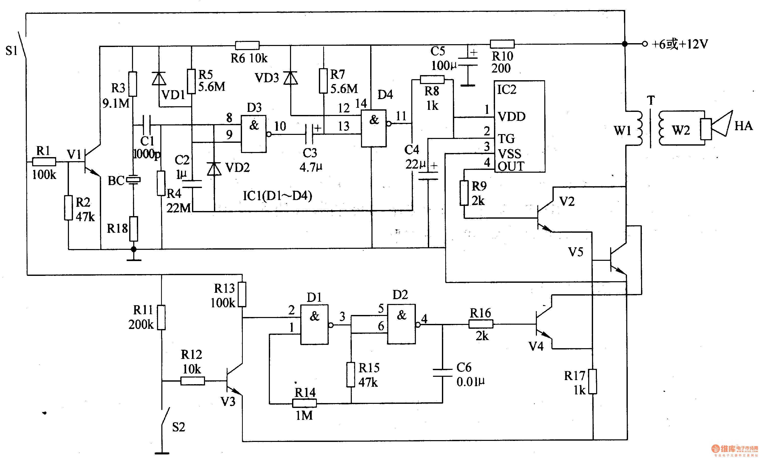
The motorcycle anti-theft alarm circuit consists of several components, including the anti-theft detection circuit, the control circuit, the sound generator, the audio oscillator, and the power amplifier output circuit, as illustrated in figure 7-91. The anti-theft detection circuit is...
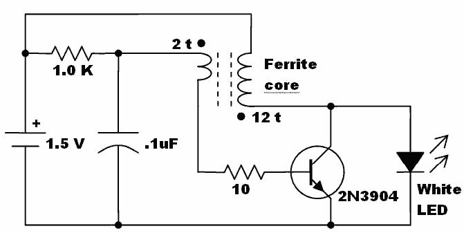
Here is an idea for a voltage booster that enables the lighting of a white LED using a single AA cell. This presents an opportunity to utilize one of the ferrite cores and white LED holiday lights mentioned in...
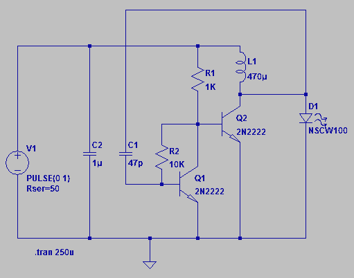
Four observations regarding the Joule Thief AA battery LED circuit. The schematic of the LED circuit illustrates the power source (V1), which symbolizes a depleted battery with only 1 volt remaining and an internal resistance. The Joule Thief circuit is...
The Joule Thief is an electronic circuit designed to utilize batteries that are typically deemed dead. A battery is often labeled "dead" when it can no longer power a specific device. However, the underlying issue is that the battery...
This post discusses blue and white LED drivers utilizing a joule thief circuit. Further exploration of the circuit's functionality is provided, along with simulation points. The joule thief circuit is a simple and efficient boost converter that allows for the...