
Motorcycle anti-thief alarm circuit (8)
")
The motorcycle anti-theft alarm circuit is designed to provide security for motorcycles by detecting unauthorized movement or tampering. The core component of the system is the anti-theft detection circuit, which utilizes a piezoelectric vibration sensor. This sensor is sensitive to vibrations and can detect when the motorcycle is being moved or tampered with.
When the sensor detects vibrations, it sends a signal to the control circuit, which processes the input and triggers the alarm system. The control circuit is responsible for managing the various functions of the alarm, ensuring that the system responds appropriately to detected threats.
The sound generator produces an audible alarm when activated, alerting the owner and potentially deterring thieves. This component is often designed to create a loud and attention-grabbing sound to maximize its effectiveness. The audio oscillator is responsible for generating the specific sound frequencies used by the sound generator, ensuring that the alarm is both effective and distinctive.
The power amplifier output circuit amplifies the audio signal from the sound generator, ensuring that the alarm can be heard over a significant distance. This amplification is crucial for the alarm's effectiveness, particularly in noisy environments where the alarm needs to be prominent.
Overall, the motorcycle anti-theft alarm circuit integrates these components into a cohesive system that enhances motorcycle security by providing real-time alerts in the event of unauthorized movement.The principle of the circuit The motorcycle anti-thief alarm circuit is composed of the anti-theft detection circuit, the control circuit, the sound generator, the audio oscillator and the power amplifier output circuit, the circuit is as shown in figure 7-91. The anti-theft detection circuit is composed of the piezoelectric vibration sensor BC, the resist.. 🔗 External reference
Related Circuits

It is said that mice are more sensitive to electromagnetic fields, which is why high-voltage grids generally yield poor results in rodent control. The electronic rodent control system described here does not use high-voltage power lines, thus it does...
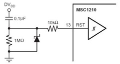
A flash memory schematic can be created using various reset sources, including power-on reset, external reset, software reset, watchdog timer reset, and brownout reset. The accompanying figure illustrates a recommended external reset circuit for the MSC1210, which includes a...
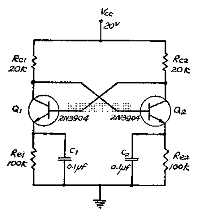
The collector and base-emitter bias of the transistor are directly coupled to each other. Each transmitter circuit controls the capacity conversion function. The emitter generates a triangular wave. The two transistors are not continuously in an active state. Instead,...

The CMOS 4060 is a 14-bit binary counter; however, only ten of these bits are connected to output pins. The 4060 also includes two inverters, which are connected in series across pins 11, 10, and 9. Together with resistors...

An electronic lock utilizing a telephone key, which is connected through a resistor plug, is integrated after the oscillator circuit's startup phase. The accuracy of the oscillation frequency determines whether the phone can be used for outgoing calls, while...
This circuit can manage nine independent telephones using a single telephone line pair located at nine different locations. It functions as a bidirectional telephone line simulator without the need for actual telephone lines, allowing for coupling, testing, and demonstration...