
joule thief circuit boosts voltage from 1.5V battery

This joule thief circuit design effectively demonstrates the principles of voltage boosting while maximizing the efficiency of LED illumination. The use of the Kemet SU9H-07010 common mode choke simplifies the construction process, eliminating the need for custom coil winding. This component, combined with the PNP transistor, allows for operation at lower battery voltages, making the circuit versatile for various applications where battery life is critical.
The integration of a voltage doubler rectifier circuit is a notable enhancement, as it allows for the full utilization of the AC pulse generated by the joule thief. By employing Schottky diodes, specifically the BAT43, the circuit minimizes forward voltage drop, which is crucial for maximizing output voltage to the LEDs. The choice of BAT43 diodes over traditional silicon diodes ensures that the circuit can deliver optimal performance, particularly in low-voltage scenarios.
In summary, this joule thief circuit exemplifies an efficient and practical solution for powering ultrabright LEDs from low-voltage sources. The design's reliance on readily available components and its ability to operate at minimal battery voltages make it an attractive option for hobbyists and engineers alike, contributing to the development of sustainable and energy-efficient electronic devices.Like all joule thieves, it boost the voltage from a single 1.5V dry cell battery and boosts it high enough to light new ultrabright GaN, blue, green, or white LEDs. But instead of requiring a custom coil, it uses an off the shelf standard Kemet SU9H-07010 (1mH) common mode choke.
Joule thieves are very common circuits found on the web. Most are based around the blocking oscillator, which goes back to the tube days. The problem is that it requires a transformer, or at least a coil with a centertap. This often means winding your own around a ferrite or powdered iron toroid. But there still exist common two coil inductors used in modern circuits. Some added features, in addition to the coil choice: (1) a PNP transistor. With a silicon transistor, this circuit can run on a battery as low as 0.7V. Germanium transistors can even operate lower. As low as 0.25V. When germanium transistors were common, they more often than not came as PNP. NPN germanium transistors were harder to make. (2) a voltage doubler rectifier, and filter circuit has been added. Usually the LED is just placed across the pulsed output. This wastes half the signal. This doubler circuit, uses the whole AC pulse generated. To waste even less, BAT43 schottky diodes are used. Even though common 1N914/1N4148 diodes will work, the BAT43, will squeeze out another half volt. 🔗 External reference
Related Circuits
The circuit is actually a half-wave rectifier. It only charges the battery on every half cycle. The plug pack doesn't like this as it leaves residual flux in the core of the transformer and causes it to overheat. But...
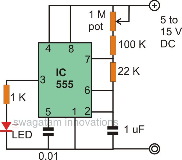
The astable multivibrator mode is the most basic operational mode of the IC 555. In this mode, it functions as a free-running oscillator. When the oscillator rate is sufficiently reduced, it can be used to drive LED lights. The...
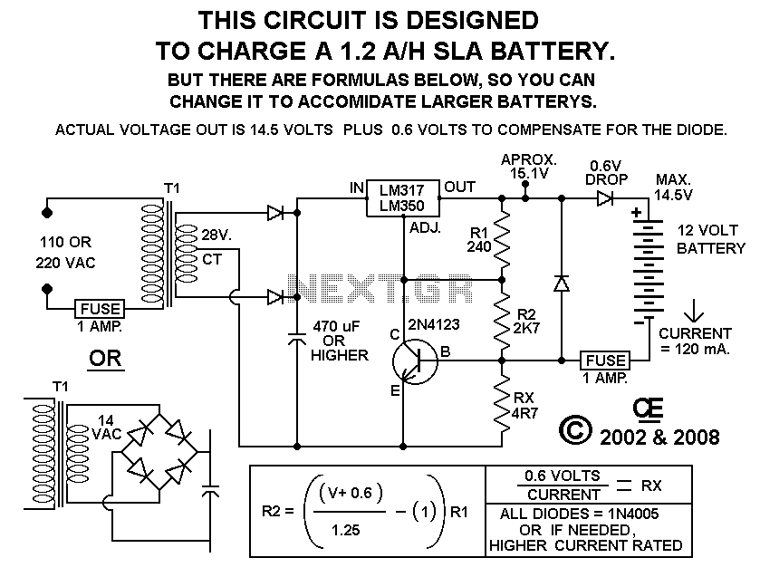
Using this circuit will give good charging results to the gel cell battery used in the metal detector or any other similar and smaller type battery. This charger is both current and voltage regulated. The output is not short...
The NE555 circuit implementation involves various connections and configurations. The circuit is designed with a supply voltage (Vcc) of +11V. The input terminal (pin 3) serves as a reset pin, and the relay and motor components are integrated into...
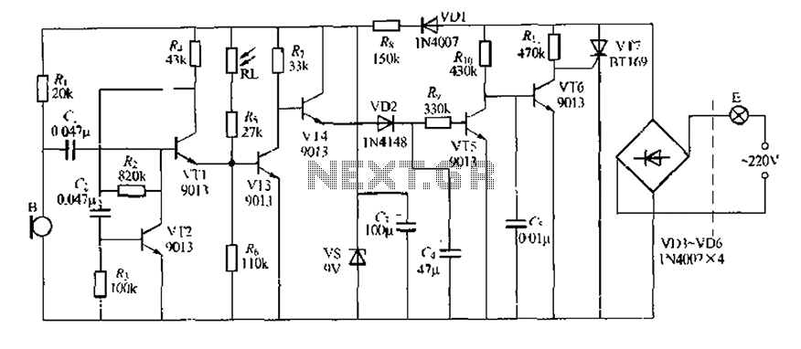
This circuit design is a sound and light control delay switch for staircase walkway lighting, featuring high voice sensitivity. In the evening, when someone walks on the stairs, their footsteps activate the electronic meter, turning on the lights. If...
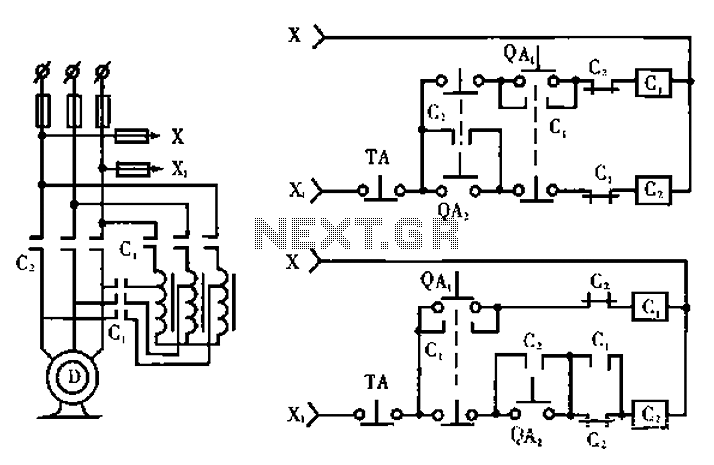
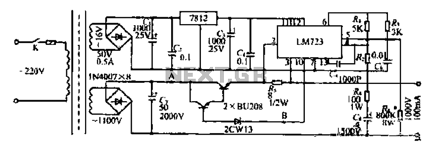
The circuit operates with relevant components highlighted in the manual's draw mode. Figure A presents a circuit schematic, while Figure B illustrates a typical conventional secondary circuit layout. Figure E showcases an improved secondary circuit schematic diagram that incorporates...