
Joule Thief inspired Boost regulator circuit

The described boost converter circuit is designed to step up a lower input voltage to a higher output voltage with maximum efficiency. It typically employs an inductor, a diode, a switch (often a transistor), and a capacitor. The fundamental operation of the boost converter is based on the principle of energy storage and transfer.
During the switch's 'on' state, current flows through the inductor, storing energy in its magnetic field. When the switch is turned 'off,' the inductor's magnetic field collapses, causing the inductor to release the stored energy. This energy is directed through the diode to the output capacitor, resulting in a higher voltage at the output than at the input.
Key components of the circuit include:
1. **Inductor**: The inductor value is crucial as it determines the energy storage capacity. A larger inductance allows for more energy storage but may affect the response time of the converter.
2. **Switch (Transistor)**: A MOSFET or BJT is commonly used as the switch. The choice of switch impacts the efficiency and speed of the circuit. Fast-switching devices are preferred for better performance.
3. **Diode**: A Schottky diode is often utilized due to its low forward voltage drop and fast switching capabilities, which improve overall efficiency.
4. **Capacitor**: The output capacitor smooths the voltage at the output, minimizing ripple. Its value must be selected based on the load requirements and the desired output voltage stability.
5. **Control Circuit**: A feedback mechanism is typically integrated to regulate the output voltage. This may involve a PWM controller that adjusts the duty cycle of the switch to maintain a steady output voltage despite variations in load or input voltage.
The efficiency of the boost converter is influenced by several factors, including the quality of the components, the design of the control circuit, and the layout of the PCB. Proper selection and integration of these elements are critical to achieving optimal performance in converting current to voltage effectively.Presented here is a significant step forward in simple, cheep, and efficient boost converter design. So to make an effective design, we must convert the current to voltage as efficiently as possible. And this circuit is very good at this as well. 🔗 External reference
Related Circuits
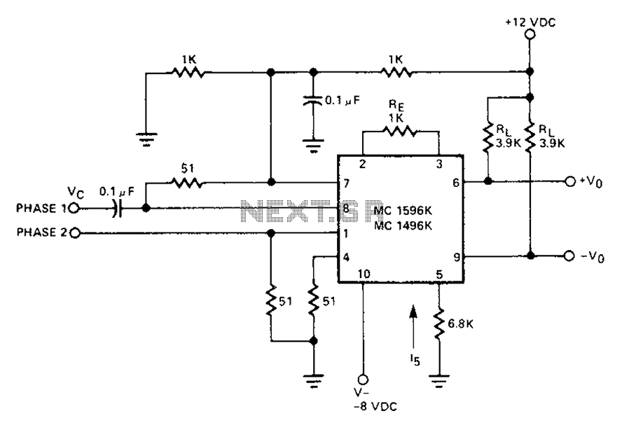
The circuit involves a Signetic balance modem connection utilizing a transistor array as a phase detector. It provides information about the cosine of the phase angle, which corresponds to the frequency of the input signal combined with the integrated...

This circuit is a robust and efficient power amplifier suitable for various audio applications. It delivers 60W RMS output at a 50V supply with an 8 Ohm load. The design is user-friendly, allowing for the use of non-critical components...
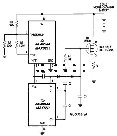
Deep discharge can damage a rechargeable battery. By disconnecting the battery from its load, this circuit halts battery discharge at a predetermined level of declining terminal voltage. Transistor Q1 acts as the switch. The overall circuit draws about 500µA...
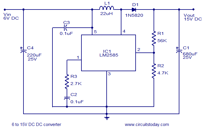
A simple and efficient 6 to 15V boost/step-up DC to DC converter based on IC L2585. This voltage converter circuit requires few external components. The circuit utilizes the L2585 integrated circuit, which is designed for high-efficiency voltage boosting applications. The...
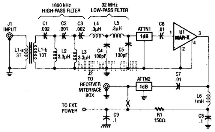
This high-frequency shortwave receiver preamplifier consists of a broadband toroidal transformer (LI-a and Ll-b), a complex LC network that includes a 1600 kHz high-pass filter and a 32 MHz low-pass filter, inductors L2 and L3 (26 turns of #26...
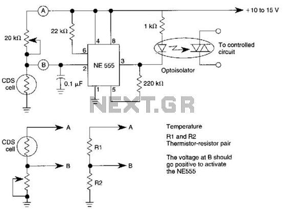
This dark-activated relay switch can be utilized to activate walkway or other outdoor lighting at dusk. By employing alternate connections to points A and B, it is capable of sensing varying levels of illumination, as well as high and...