
6V to15V DC to DC converter using LM2585 wired in the boost mode

The circuit utilizes the L2585 integrated circuit, which is designed for high-efficiency voltage boosting applications. The L2585 operates by converting a lower input voltage (ranging from 6V to 15V) to a higher output voltage, making it suitable for various applications where higher voltage levels are required from a lower voltage source.
The essential components of this circuit include the L2585 IC, an inductor, a diode, and capacitors. The inductor is used to store energy when the switch inside the L2585 is closed and releases it when the switch opens, effectively stepping up the voltage. The diode is placed in the output path to prevent backflow of current, ensuring that the output voltage remains stable. Capacitors are used at the input and output to filter voltage ripples and stabilize the output voltage.
In terms of configuration, the circuit requires careful selection of the inductor and capacitors to match the desired output voltage and current specifications. The feedback mechanism within the L2585 regulates the output voltage by adjusting the duty cycle of the internal switching, ensuring efficient operation across varying load conditions.
This boost converter circuit is particularly advantageous in battery-powered applications where maximizing the available energy from lower voltage sources is critical. Its simplicity and efficiency make it a preferred choice for powering devices that require a higher operating voltage without the need for complex circuitry.A simple and efficient 6 to 15V boost/stepup dc to dc converter based on IC L2585. This voltage converter circuit requires few external components.. 🔗 External reference
Related Circuits
New applications for DC voltage converters, such as the LT1070, arise every day. These converters can be adapted to nearly every imaginable ratio of input and output voltages. However, all of these circuits and devices share a common shortcoming:...
This bell ring generator utilizes the MC14106 or 40106 hex Schmitt inverter IC to produce a dual-tone ringing sound akin to that of standard doorbell units. The circuit design of the bell ring generator is centered around the MC14106 or...
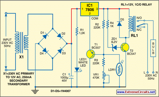
Voltage regulator ICs (78xx series) provide a steady output voltage against a widely fluctuating input supply when the common terminal is grounded. Any voltage above zero volts (ground) connected to the common terminal is added to the output voltage,...
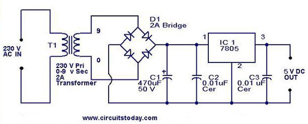
A 5V power supply using IC 7805 is designed and explained with a neat circuit diagram. The circuit for a 5V power supply utilizing the IC 7805 voltage regulator is a straightforward and efficient design that provides a stable output...
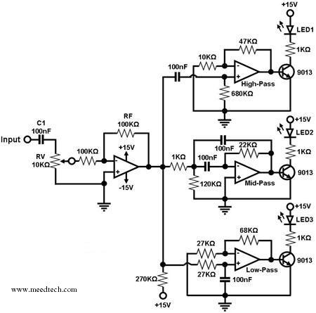
A simple circuit for converting an audio signal (such as one that comes from the output terminals of a CD player). The circuit basically consists of a buffer/amplifier stage and three filter circuits: a high-pass filter, a mid-pass filter,...
The schematic indicates that the AccelR8 utilizes only three integrated circuits (ICs). An AVR 8515 microcontroller performs the computational tasks and manages the other circuits. A MAX603 regulates voltage and controls the power-on and power-off functions. The key component...