
KD-1001 produced by lantern controller

The circuit operates with a primary input of 220V AC, which is reduced by the resistor R1 to ensure safe operation of the downstream components. The rectification process is performed by the diode VD1, converting the AC voltage to DC. The capacitor C1 smooths the rectified voltage, providing a stable 3V DC output suitable for powering the KD-1001 manifold.
The manifold's trigger mechanism is crucial for its operation. When the switch SB is in the off position, the circuit interrupts the power supply, stopping the manifold from functioning. However, the resistor R2 provides a small current to the gate of the SCR, allowing it to remain in a conductive state. When the switch is turned on, the KD-1001 activates, allowing the output terminal Q to pulse in a rhythmic manner, effectively controlling the SCR's gate current. This pulsing action creates a flashing effect in the connected lantern.
The design also incorporates an audio output feature. By connecting a piezoelectric ceramic sheet B to the system, the blinking state of the lights can synchronize with electronic music output, enhancing the visual and auditory experience. The overall configuration allows for versatile control over the lighting and sound output, making it suitable for various applications where both illumination and audio feedback are desired. The circuit's ability to toggle between steady and flashing states provides flexibility for different operational scenarios.220V AC power via a resistor Rl buck, VDI rectifier, VD2 and Cl filtered output voltage of about 3V DC voltage supply manifold KD-1001 electricity. Manifold trigger terminal co nnected to the positive terminal of the power source to form a continuous sound and light output. Energized after, when the switch is off SB, Manifold does not work, the power supply via a resistor R2 to vs SCR gate trigger current injection, vs opened, H powered lantern lit. If the switch is closed SB, music Manifold KD-IOOI power work, manifold Q output terminal on the negative side modulation pulse rhythmically pulling vs SCR gate current, resulting in time vs time off on, lights H flashes light.
So you can choose two lanterns lit with flashing light emitting state by the switch SB. When lights blinking state, connected to the audio output of the piezoelectric ceramic sheet B can issue a pleasant electronic music sound.
Related Circuits
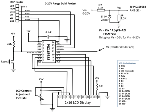
This project details the construction of a digital voltmeter utilizing a PIC microcontroller. A character-based HD44780 LCD display is employed to visualize voltage measurements. The microcontroller selected for this project is the PIC16F688, which features 12 I/O pins, with...
The paraphase configuration is noteworthy for its ability to adjust either treble or bass, but not both simultaneously. The adjustments made to the tone controls directly influence the slope of the frequency response and the extent of bass and...
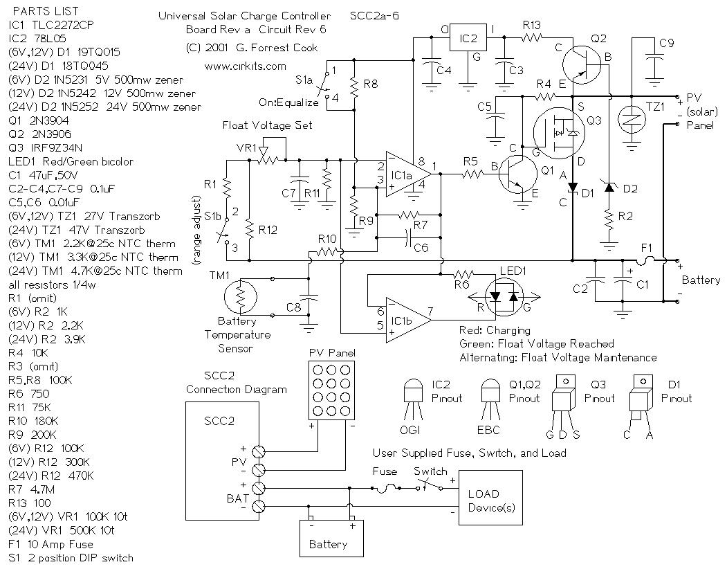
The SCC2 is a solar charge controller designed to manage the power transfer from a photovoltaic panel to a rechargeable battery. It includes a straightforward setup process utilizing a single potentiometer for adjusting the float voltage, an equalization function...
This power factor controller accepts voltages ranging from 90 to 268 Vac, which is why it is referred to as a power factor controller with universal input, as it accommodates the mains supply standards in nearly any country. The...
A circuit is being designed to drive a 4x7 segment display using a PIC microcontroller. The previous implementation utilized four pins to control each of the four digits individually, with a sequential activation method. The designer aims to simplify...
This AC drill speed controller circuit schematic allows for the control of the drilling speed of a borer or drilling machine. This project is based on the principle that... The AC drill speed controller circuit is designed to modulate the...