
Paraphase Tone Controller circuit

The paraphase configuration is an audio processing circuit designed to manipulate frequency response characteristics selectively. Its primary function is to allow for independent adjustments of treble and bass frequencies, which is beneficial in audio applications where specific tonal qualities need enhancement without affecting the overall balance of sound.
The circuit comprises two distinct networks, each consisting of capacitors and resistors that work together to shape the audio signal. The first network, formed by capacitors C1, C2, and C3 in conjunction with resistors R9, R10, and R11, is responsible for one channel of the audio signal, while the second network, comprising capacitors C5, C6, and C7 paired with resistors R12, R13, and R14, handles the other channel.
The configuration allows for the adjustment of either treble or bass by altering the resistance values or capacitance in one of the networks, thereby affecting the frequency response curve. The slope of this curve is determined by the difference in settings of the tone controls, which provides a precise means of tuning the audio output to the listener's preferences.
This design is particularly advantageous in applications where space and component count are critical, as it simplifies the circuit while providing effective control over audio characteristics. Additionally, the paraphase configuration can be integrated into various audio devices, including mixers, amplifiers, and equalizers, enhancing their functionality and user experience.This unique property makes the ˜paraphase configuration of interest if only treble or bass needs to be adjusted - it is not possible to adjust both at the same time! Essentially, it s the difference in setting of the tone controls that determines the slope of the frequency response, and the degree of bass/treble correction.
The circuit is simplicity itself, based on two networks C1-C2-C3/R9-R10-R11 and C5-C6-C7/R12-R13-R14.. 🔗 External reference
Related Circuits
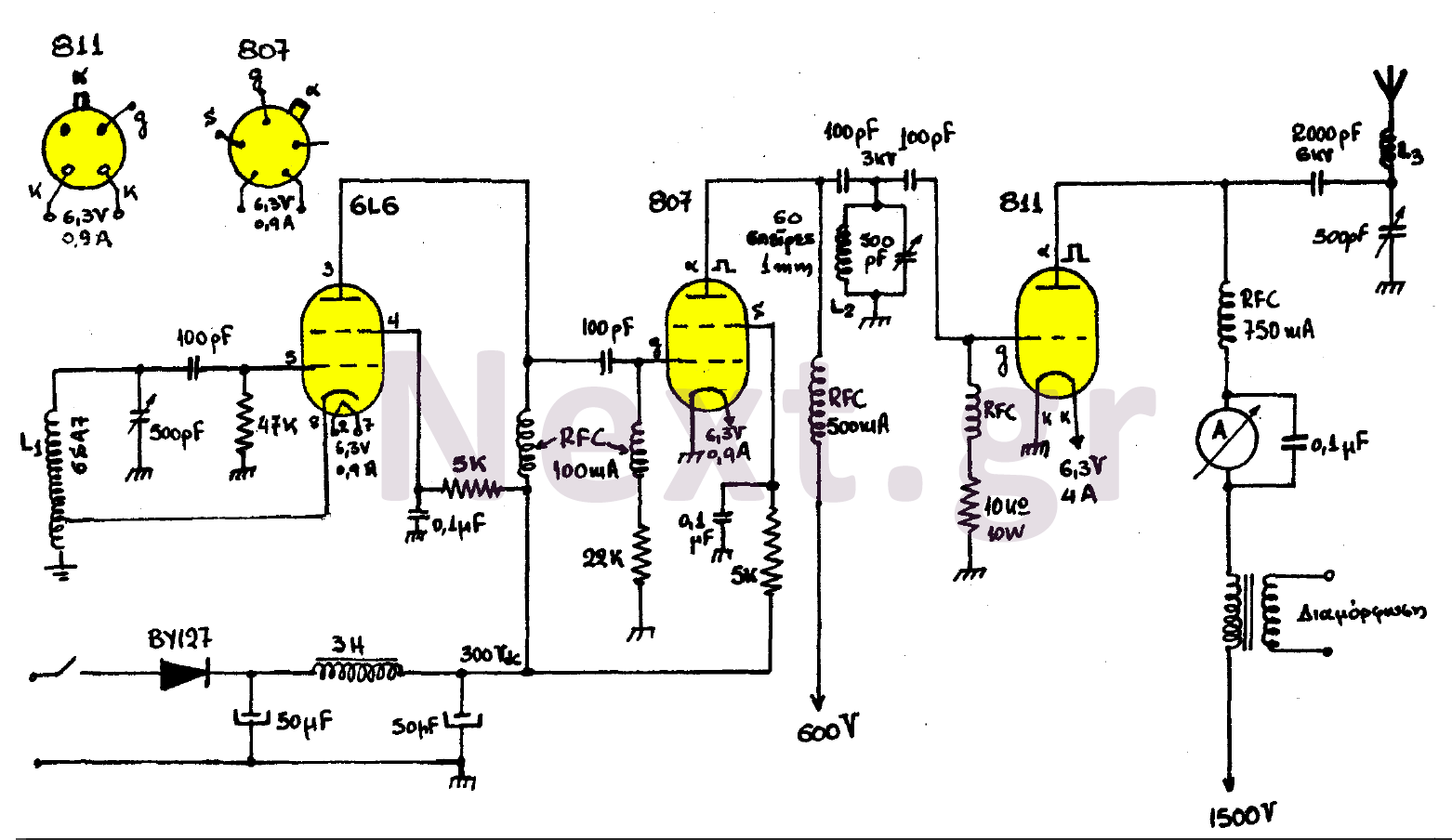
This transmitter consists of three stages: the oscillator stage utilizing a 6L6 tube, the amplifier isolator stage with an 807 tube, and the final stage of the transmitter featuring an 811 tube. The coil L1 is specified by the...
A varying brightness AC lamp circuit utilizes a silicon-controlled rectifier (SCR) to gradually adjust the intensity of a 120-volt light bulb by controlling the duration of AC line voltage applied to the lamp during each half cycle. The circuit...
This circuit addresses the challenge of transmitting data over a cable that lacks available conductors. The data is modulated using On-Off Keying (OOK) and superimposed on a high-frequency carrier, allowing it to be transmitted over a low-voltage power supply...
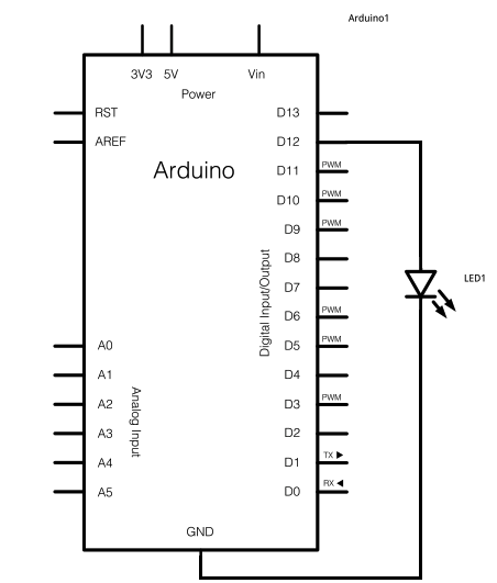
The schematic for this project consists of adding a single 5mm LED to one digital output port on the Arduino. The main components in the schematic include the Arduino Uno, a 5mm LED, and a USB cable. The left...

This board layout was created using the SOIC version of a PIC16F627A without drawing the usual schematic first. Most of the part values are etched on the Layout. The SIP resistor packs I used are 10k ohm, some experimentation...
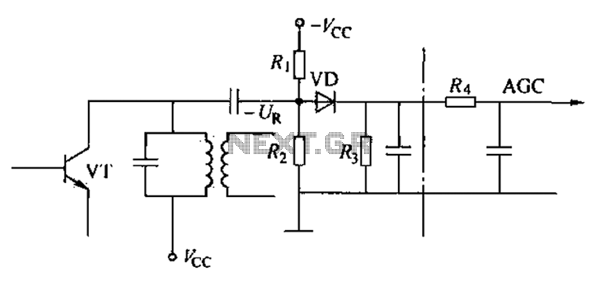
Commonly referred to as an automatic gain control (AGC) circuit, it is primarily utilized in receivers. This circuit maintains a constant output voltage amplitude despite variations in the input signal amplitude. It ensures that the receiver can effectively process...