
PIC16F688 Based Digital Voltmeter with a PIC mictocontroller

The digital voltmeter circuit utilizes the PIC16F688 microcontroller, which is well-suited for this application due to its integrated ADC capabilities and sufficient I/O pins for interfacing with the LCD display. The HD44780 LCD is commonly used for displaying alphanumeric characters, making it ideal for showing voltage readings in a user-friendly format.
The resistor divider network, composed of resistors R1 and R2, plays a crucial role in scaling down the input voltage. The values of these resistors must be carefully calculated to ensure that the maximum voltage of 20 V is reduced to a safe level of 5 V for the ADC. The formula for the voltage divider is given by:
V_out = V_in * (R2 / (R1 + R2))
Where V_out is the voltage across R2 (input to the ADC), and V_in is the input voltage (up to 20 V). Choosing appropriate resistor values will ensure that the input voltage remains within the acceptable range for the microcontroller.
The zener diode serves as an essential protective component, safeguarding the microcontroller from overvoltage conditions. If an input voltage exceeds the specified limit, the diode will conduct and clamp the voltage to a safe level, thus preventing damage to the PIC16F688.
The firmware for the PIC microcontroller will need to be developed to read the ADC values and convert these readings into a voltage display format suitable for the LCD. The 4-bit mode of the LCD will reduce the number of I/O pins required for communication, allowing for efficient use of the available pins on the microcontroller.
In summary, this digital voltmeter project combines a PIC microcontroller with an LCD display and a resistor divider network to measure and display voltages up to 20 V safely and effectively. The design emphasizes the importance of component selection and protective measures to ensure reliable and accurate voltage measurements.This project describes how to make a digital voltmeter with a PIC microcontroller. A character based on HD44780 LCD display is used to measure voltage. The PIC microcontroller used in this project is PIC16F688, which has 12 I / O pins of which 8 can be used as analog input channels to the built-in 10-bit ADC. The measured voltage is fed to one of eight analog channels. The reference voltage for the AD conversion is chosen to be the supply voltage Vdd (+5 V). A resistor divider network is used to end the inning with a map of the range of input voltage range of ADC input voltage (0-5 V). The technique can show that the input voltage from 0 to 20 V, but can be expanded with an appropriate choice of resistance and make the calculation described below.
Since the PIC port can not be directly 20V input, the input voltage is reduced by using a resistor divider network simple. The resistors R1 and input voltage range R2-range of 0-20V to 0-5V, before being implemented in PIC16F688 channel analog input AN2.
5. 1V zener diode connected in parallel between the port pin AN2 and earth provides protection to the PIC pin input voltage is accidentally beyond 20V. The LCD screen is connected to the 4-bit mode, and the head of CPSI makes firmware development easier than you can reprogram and test the PIC while it is on.
When you`re happy and you want to transfer the circuit of the test card to a PCB or prototyping board for general purposes, it is not necessary ICSP header. 🔗 External reference
Related Circuits
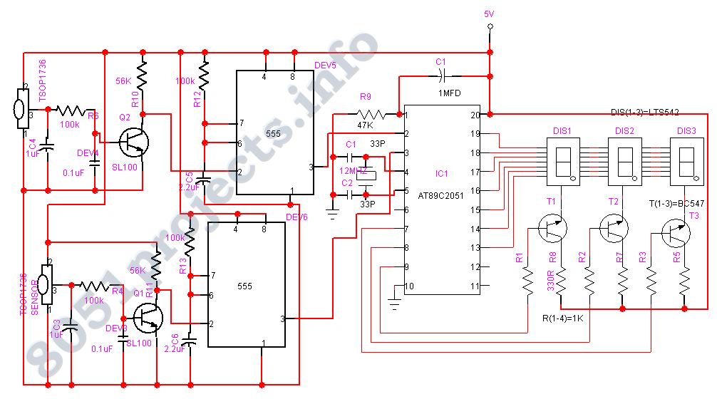
The AT89C2051 Digital Visitor Counter utilizes a microcontroller to perform its function by receiving signals from sensors. The AT89C2051 Digital Visitor Counter is designed to accurately count the number of visitors entering or exiting a designated area. This system employs...
With the advancement of technology and the widespread use of large high-accuracy dynamic range D/A converters for full-speed digital signal processing, the generated frequency remains relatively fixed due to the phase control achieved through digital means and adjustable synthesis...
National Instruments Multisim now features microcontroller unit co-simulation capabilities, enabling the inclusion of a microcontroller, programmed in assembly or C code, within SPICE-modeled circuits. The MCU functionality in Multisim allows students, educators, and professional users to program MCUs in...
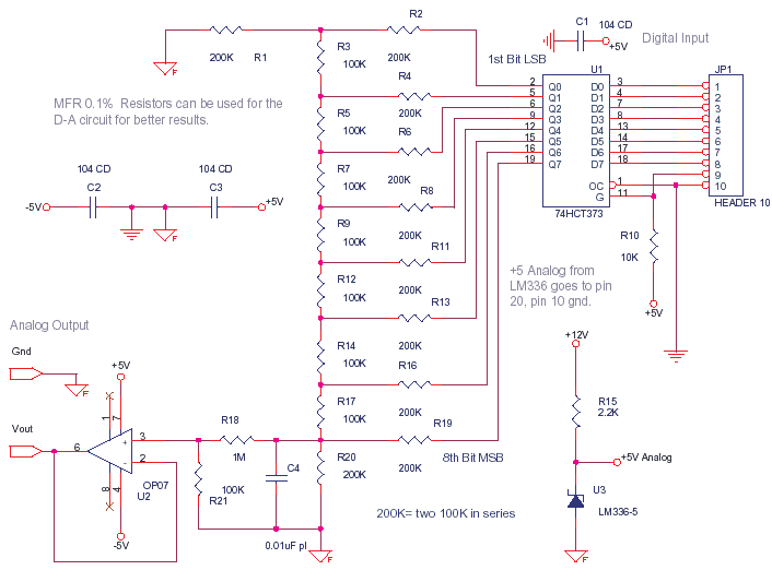
This circuit can be utilized to convert a byte sent from a microcontroller into an analog value, such as 1.51 V. At full scale, when all 8 bits are high, it is calibrated to provide 2.55 V, with each...
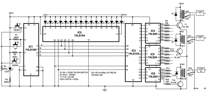
This circuit is capable of controlling one out of 16 devices using two push-to-on switches. An up/down counter functions as the master controller for the system, and visual feedback is provided through LEDs. The circuit employs IC1 (74LS193), which...
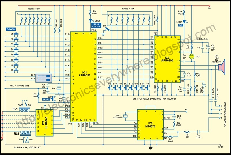
A circuit that allows for the operation of home appliances such as lights and water pumps from a remote location, such as an office. This system enables users to turn off appliances with their cellphones if they forget to...