
Keyboard Matrix Interface

Keyboards can be categorized based on their switch connection methodology into two main types: common connection keyboards and matrix connection keyboards. The matrix configuration is particularly advantageous as it significantly reduces the number of required connections, which is beneficial for integration with various integrated circuits (ICs) specifically designed to interface with matrix keyboards.
In contrast, keyboards with a common connection often feature individual connectors for each key, presenting a different challenge when interfacing with ICs that are optimized for matrix configurations. To bridge this gap, electronic switches are utilized. Each key on the keyboard effectively controls one of these electronic switches, which are arranged in a matrix layout.
For example, a hexadecimal keyboard can be structured as a 4x4 matrix, where each position in the matrix corresponds to a specific key. The electronic switches in this configuration are typically held in an open state by pull-down resistors, which ensure that the switches do not inadvertently close and create false signals. The current drawn by this arrangement is minimal and is predominantly determined by the resistance values of the pull-down resistors and the number of keys that are simultaneously pressed.
Notably, CMOS (Complementary Metal-Oxide-Semiconductor) switches are particularly well-suited for this application due to their extremely low power consumption, effectively drawing negligible current during operation. This characteristic makes them ideal for battery-powered devices, where power efficiency is paramount. The combination of matrix switch arrangement and low-power CMOS technology thus creates an efficient and effective keyboard interface solution. Keyboards can be slotted into two categories, at least as far as the manner that the switches are connected is co ncerned: those with a common connection and those with the switches arranged in a matrix. The matrix type has the important advantage that the number of connections is an absolute minimum. Such an arrangement is ideal for ICs; many of these are designed for use with a matrix keyboard. However, many keyboards are available in job lots, for instance, that apart from a common connection also have a connector for each key. Such keyboards can be connected to ICs that require a matrix type with the aid of a number of electronic switches.
The principle is straightforward: each key of the keyboard controls an electronic switch that is included in a matrix. As an example, the diagram shows a hexadecimal keyboard that is arranged in a 4- -4 matrix. Each of the electronic switches is held in the open position by a pull-down resistor. The current drawn by the circuit is very small and is determined mainly by the value of the pull-down resistors and the number of keys being pressed.
The CMOS switches draw virtually no current.
Related Circuits

If you are developing applications for the PIC MCU and miss debugging tools or don't have enough I/O pins for a parallel LCD interface in your design, this serial interface can help print debug messages and/or reduce the pin...
An external piezoelectric element has been added for placement on a bench top, making it more accessible for children. This external piezo element was soldered to the same pads as the built-in piezo element of the Tap-Tempo Metronome. A...

This is a design of the circuit diagram for an RS422 interface. Connector K1 is connected to the serial port of the PC, and power for the PC side of the circuit is obtained from the signal lines DTR...
Control RGB LED strips via a USB or Ethernet interface. These strips consume a significant amount of power, and the mass-produced controllers are inadequate. The goal is to have independently controllable "zones," allowing this device to power one or...

A low-cost, low-part-count MIDI to Trigger interface with 10 outputs. This MIDI to Trigger interface generates a TTL (5V) trigger signal for each note across a range of ten notes. It can be utilized, for instance, as a MIDI...
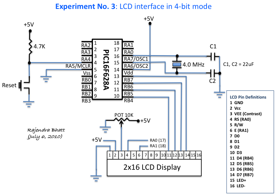
An HD44780 Character LCD is a liquid crystal display (LCD) device designed for interfacing with embedded systems. These screens are available in various configurations, including 8x1 (one row of eight characters), 16x2, and 20x4. The most commonly produced configuration...