
Drum Solenoid Interface for Tap-Tempo Metronome

The circuit design incorporates a microcontroller interfacing with an electromagnetic solenoid through a TIP120 transistor. The microcontroller controls the solenoid operation by outputting a digital signal to the base of the TIP120, which acts as a switch. The solenoid operates at 12V, necessitating an external power supply that can provide sufficient current. The inclusion of a large electrolytic capacitor ensures that the solenoid receives the necessary current during activation, while the protection diode safeguards the circuit from inductive kickback when the solenoid is deactivated. The resistor serves to limit the current flowing into the microcontroller pin, preventing damage to the microcontroller from excessive current. The firmware update enhances the functionality of the metronome, allowing for improved control and operation. The careful disconnection of pin 12 from the seven-segment display ensures that the microcontroller can effectively manage the solenoid without interference from other components. This comprehensive circuit design illustrates the integration of various electronic components to create a functional and safe metronome system suitable for educational purposes.We added an external piezoelectric element to set on the bench top, making it easier for kids to reach. We simply soldered this external piezo element to the same pads as the Tap-Tempo Metronome`s built-in piezo element.
Here`s the large piezo we used. For the drum striker, we used an electromagnetic solenoid, which consists of a coil of wire wound around a movable metal core. When current is sent through the coil, the metal core moves a short distance. Unfortunately, the pins on a microcontroller are relatively weak, meaning that they can only supply 20-40 milliamps (mA) of current, compared to the 1 amp draw of our solenoid. This means that we can`t directly connect the microcontroller to the solenoid, as not enough current would be supplied.
The usual solution to this drive strength problem is to use a transistor as a switch. Here`s a very common way to drive a large inductive load from a microcontroller. Since the solenoid requires a higher supply voltage, 12v in our case, we need to account for the extra power supply. In this circuit, we use a transistor that can easily handle the current through the solenoid (1A). We used a TIP120, which is a kind of power transistor that can be treated like a NPN bipolar junction transistor (BJT) and can handle up to 5 amps of current, more than enough for our 1A solenoid.
While this circuit is very common, the diagram is based on an example diagram from the Arduino Playground (PDF). When the output pin from the microcontroller is driven high, the path between the top and bottom terminals of the transistor are connected, allowing current to flow through the solenoid.
When the output pin is driven low, no current flows through the transistor, stopping the solenoid. The large electrolytic capacitor is very important, as it is used to help supply the large current draw of the solenoid. The capacitance should be at least 1000 uF. The resistor is used to limit current through the pin. One very important part of this circuit is the protection diode. A diode is a special piece of silicon that only conducts electricity in one direction. Solenoids, relays, and motors are essentially just big coils of wire that generate magnetic fields when current is flowing through them.
Sometimes a coil of wire is called an inductor. When the current stops flowing through the coil, the magnetic field tries to keep the current flowing, and actually pushes more current through the wires, a phenomenon called inductive kickback. This current push can be dangerous to the transistor and microcontroller, so we have to add the protection diode.
Update the firmware to version 1. 15. This firmware beeps and displays 15 ³ on startup, and generates the necessary pulses on pin 12 for each beat. If you have access to a PIC programmer, you can update your metronome with the new firmware available from the download page.
We are working to upgrade our online marketplace to allow us to sell updated PIC microcontrollers. Check back soon for more details. The output pin, pin 12, is normally connected to the unused decimal point LEDs in the seven-segment displays. We can easily disconnect it by cutting a trace with a sharp knife, such as an X-Acto knife. Carefully cut the trace by moving the blade over it multiple times. Be careful not to cut the adjacent traces. Keep cutting until you can see the gap between the two sides. If you have a multimeter, you can make sure that there is no continuity between pin 12 on the chip and pin 7 on the seven-segment displays.
Connect a wire to pin 12 on the chip. You can do this easily by taking a length of breadboard wire and forming a tiny loop in one end. Remove the chip from t 🔗 External reference
Related Circuits

This combination sync stripper and universal video interface can solve various problems, including interfacing Super Nintendo with other devices, video overlay, and locking TV frames for scopes. Kits, fully tested units, and custom cable assemblies are available through Redmond...
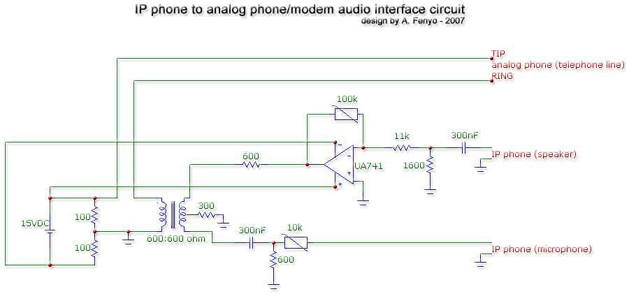
The transformer is a 600:600 ohm transformer, also referred to as a 1:1 ratio 600 ohm transformer. It has approximately the same number of turns on both the primary and secondary coils and is optimized for operation at a...

This simple 220V power interface is designed for monitoring electrical equipment and devices using a computer. The interface only detects whether the monitored device is powered on or off. A key feature of this circuit is the galvanic isolation...
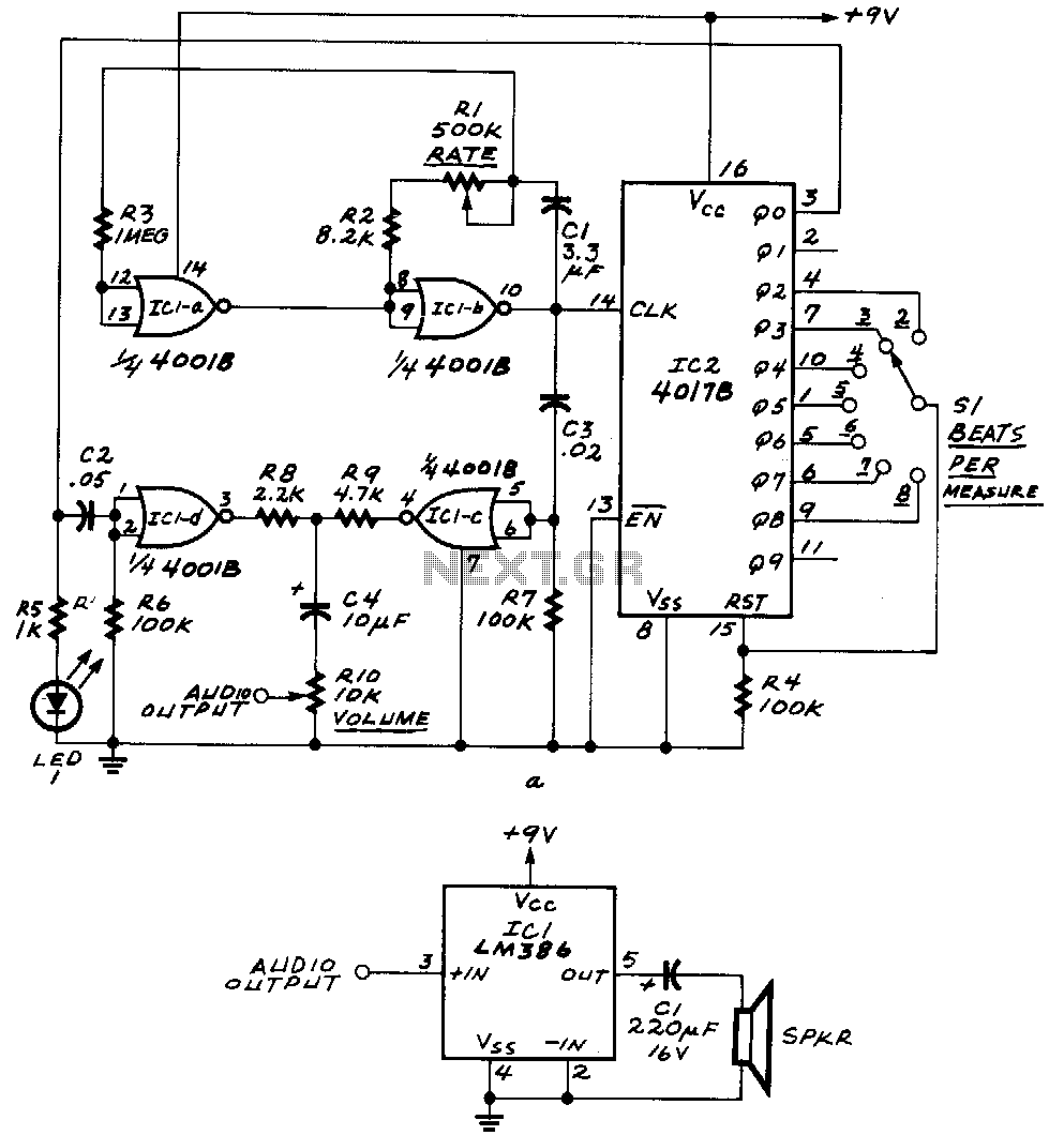
ICla and IClb form an astable multivibrator. The astable's signal is fed to IC1c, as well as to the clock input of IC2, a 4017B decade counter. The outputs Q0 through Q9 of that IC become high one at...
This interface circuit provides electrically isolated RS422 communication interface to the PC serial port. The isolation circuit protects the PC from direct connection to hazardous voltages. More: Figure 1 shows the circuit diagram of RS422 interface. Connector K1 is...

The computer control system is designed to detect signal path switching, requiring multiple input interface expansions. This system can switch all signal inputs into the computer. By utilizing a programmable chip, the 8255 expansion input interface allows for three...