
Keyless Entry Arduino

The described circuit involves a matrix keypad configuration, which is a common method for interfacing multiple keys with a limited number of input/output lines. In this case, the keypad utilizes a 3x4 matrix, consisting of 3 rows and 4 columns, enabling the detection of 12 keys using only 7 wires.
When a key is pressed, such as the number 8, it connects a specific row to a specific column. For example, pressing the number 8 connects ROW3 to COL2. The microcontroller continuously scans the rows and columns to identify which key is pressed by checking for a voltage change on the corresponding row and column lines.
To implement this, the microcontroller can be programmed to set each row to a low state sequentially while reading the column states. When the microcontroller sets ROW3 low, it will check COL2 for a low signal. If detected, it confirms that the key corresponding to that intersection (in this case, the number 8) has been pressed.
This efficient method reduces the number of required input lines, allowing for a compact design while still providing the functionality of a full keypad. The remaining wires are utilized for the other rows and columns, ensuring that the microcontroller can accurately detect all key presses within the matrix configuration.Example if you press number 8 it will effect the wire ROW3 and CLO2. By this the microcontrollercan determine what key was pressed with only 7 wires from the keypad. 🔗 External reference
Related Circuits
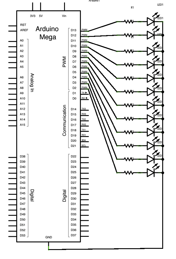
Connect the longer, positive legs (anodes) of 12 LEDs to digital pins 2-13 through 220-ohm current limiting resistors. Connect the shorter, negative legs (cathodes) to ground. The circuit will sequentially illuminate each LED from the lowest pin to the...
The figures above illustrate the fundamental concept of a robot, which comprises input and output devices connected to a central processing unit, often referred to as the brain. In this case, the Arduino acts as the brain, controlling all...

An attempt at an Arduino guitar pedal. The guitar signal feeds through a PT2399 delay circuit, modified to include a JFET preamp phase. The delay circuit has Echo and Delay knobs. From there, it feeds into an optoisolated-Arduino-5V preamp,...
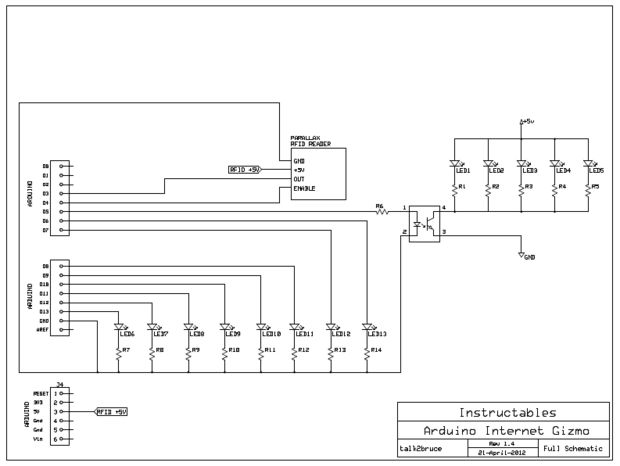
The Arduino Internet Gizmo comprises an Arduino, an RFID card reader, several LEDs, and various components housed within a repurposed PC power supply case. The Arduino Internet Gizmo is a versatile electronic project designed to facilitate Internet connectivity and RFID...
This device transmits data regarding the state of an office to Twitter, as it is deemed slightly more relevant than sharing similar information about a residence. It holds potential significance for biodiversity-related activities, especially when integrated with long-range WiFi...
This Arduino sketch is designed to recover ATtiny microcontrollers that have become non-functional due to incorrect fuse settings. It achieves this by placing the affected ATtiny into high-voltage serial programming mode and rewriting the fuses to safe values. The...