
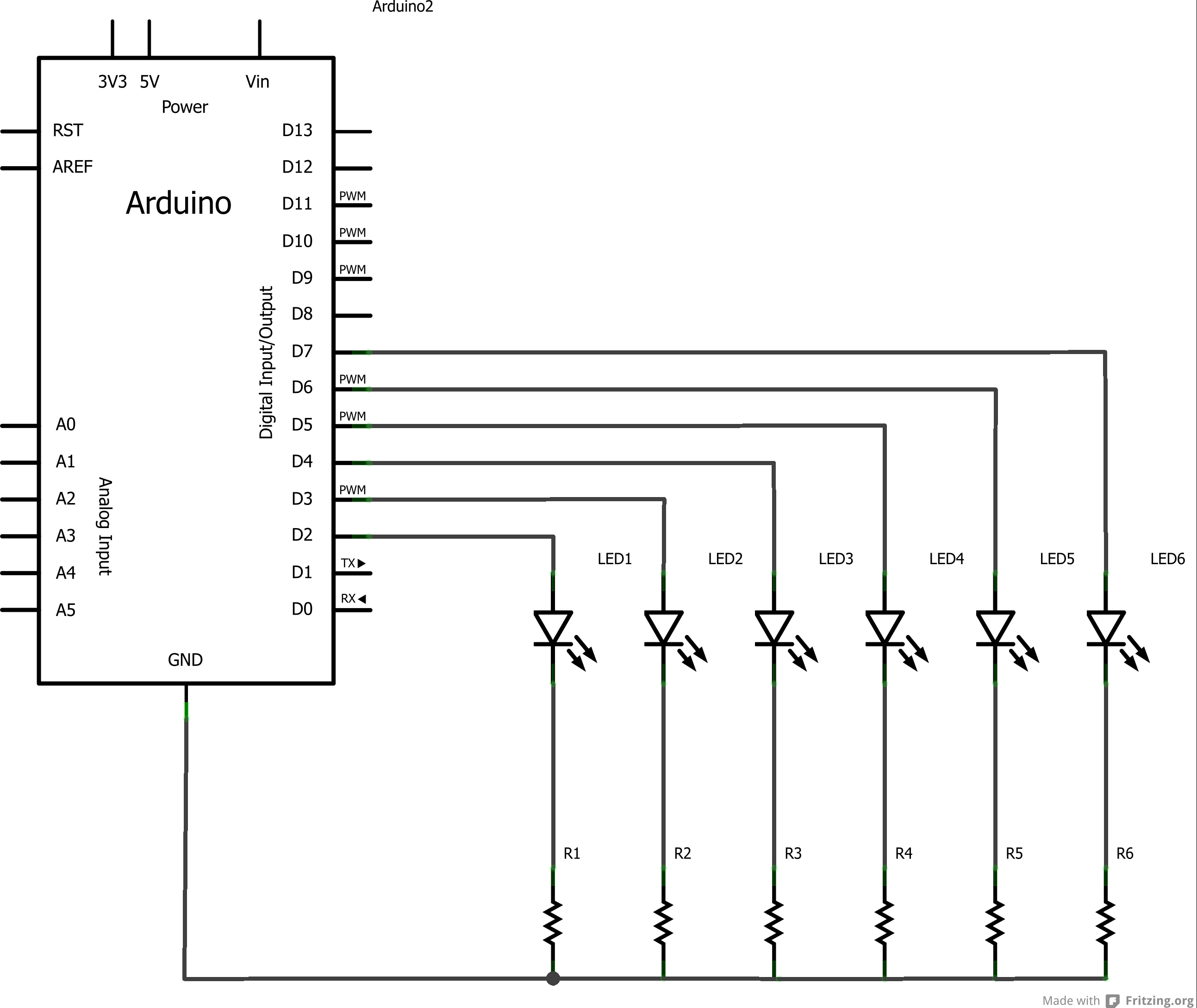
Light Follower Robot using Arduino

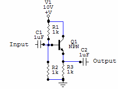
In the circuit on the left, the LED remains off due to the high resistance of the LDR without light, keeping the transistor in a cut-off state. When light is directed onto the LDR, its resistance decreases, resulting in base polarization that allows the transistor to conduct and turn the LED on. Conversely, in the circuit on the right, the LED is initially on because the LDR's resistance exceeds the combined resistance of a 10KΩ resistor and a 10KΩ potentiometer, thus polarizing the transistor and driving the LED. When light falls on the LDR, its resistance drops, leading to a reduction in current that turns the transistor off, switching the LED off. In the BUGBot design, DC motors are employed to control the transmission system (including the gearbox and wheels), enabling the robot to follow the light detected by the sensors. Merely detecting light and toggling the motors on or off is insufficient; the motors must be powered for a minimum duration to ensure proper operation. For the motor driver, which only requires unidirectional rotation, an H-bridge is unnecessary; instead, Darlington transistors can be utilized effectively.
The described robotic system leverages the Arduino platform as a central processing unit, orchestrating the interactions between various components. The LDRs serve as critical input devices that detect light intensity, providing feedback to the Arduino for decision-making. The varying resistance of the LDRs, influenced by light exposure, allows for precise control of the robot's behavior.
The implementation of transistors in the circuit is essential for controlling the LED indicators based on the light detected by the LDRs. The use of Darlington transistors in the motor driver circuit simplifies the design while ensuring efficient control of the DC motors. The configuration allows for effective operation without the complexity of an H-bridge, making it suitable for applications where motors are required to run in a single direction.
The overall circuit design integrates the sensors, processing unit, and actuators to create a responsive robotic system capable of light-following behavior. The motors' control strategy, which includes maintaining power for a sufficient duration, ensures that the robot can navigate its environment effectively. This design exemplifies the intersection of sensor technology, microcontroller programming, and motor control in robotics, providing a foundational understanding for further advancements in robotic applications.The figures above shows the basic idea of any robot, where we have some inputs and output devices connected to the brain and some outputs controlled by the brain. In our case we will have the Arduino like the brain. The central Brain, controls all movements of the Robot. The sensors will do the monitoring where the light focus is and finally the m otors that gives to the robot its movements to go forward, to turn left and to turn right. The input devices will be LDRs (Light Dependent Resistor) those components have its resistance changed according to the incidence of light on the device. Basically, if there is no incident light, the LDR will have a high resistance (from 200K © to 5M © more or less), and when the incidence of light the LDR will have a reduced resistance (since some dozens of ohms to rough a few hundreds) as we can see in the LDR`s characteristic curve above In the circuit on the left, initially we can note that the LED is off because the resistance of the LDR without incident light, let the transistor in cut state.
When we line up the light focus on the LDR, it will decrease its resistance and thus we have a base polarization, and so the transistor enter in the conducting state, switching the LED on. In the circuit on the right, we will notice that the LED is initially in the state on, since we have no incident light on the LDR and the LDR have a resistance greater than the sum of resistances of the resistor of 10K + the 10K potentiometer; the transistor base will be polarized driving the LED, and when the light falls on the LDR, the LDR will have a decrease in current and will sustain the transistor into the cut state switching the LED off.
In our BUGBot, we use DC motors to control transmission system (gearbox and wheels) so that the robot can move and so follow the incident light on the sensors. It is not sufficient only to detect the presence of light on the sensors and drive the motors on/off, the motors must also keep powered by an amount of time for minimum operation.
For the motor driver (as they must rotate only in one direction), it is not necessary to use an H-bridge, we can do the motor driver using only Darlington transistors. 🔗 External reference
Related Circuits
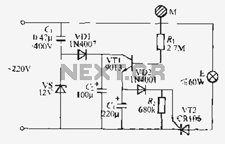
Utilize the call sheet to touch the electrical threshold M, which causes the E lamp to light up. When the same interval subparagraph is triggered, the lights will automatically turn off. A voltage regulator rectifier circuit is formed using...
A challenge encountered when beginning to work with Arduino was determining how to create circuit diagrams for projects. There are numerous software options available for drawing schematic diagrams, some of which are free while others require payment, each presenting...
A simple calling bell circuit designed for small offices to summon the office boy using an existing intercom system. The office boy can be called from up to nine locations equipped with extension lines. The system connects to a...
Constantly changing light and sound analog controller circuit 02 The circuit described is an analog controller designed to modulate light and sound in a dynamic manner. It typically utilizes components such as operational amplifiers, resistors, capacitors, and transistors to achieve...
Two examples of the most common types of Voltage followers (buffers). You can find some theory behind them in our amplifier gain and buffer amplifier pages. This first circuit is a very simple one transistor voltage follower. Consists of...
Fortunately, my trusty Arduino came to the rescue. I created an Arduino-based AVR programmer that uses the high voltage programming mode and can fix pesky fuses like RSTDISBL. The Arduino has just enough IO to implement the entire HV...