
Kirlian Photography power supply

The CD4049 is a hex inverter that can be configured to operate as a multivibrator, generating square wave signals. In this application, the CD4049 outputs are connected to the bases of a Darlington pair, which consists of two bipolar junction transistors (BJTs) configured to amplify current. This arrangement allows for significant current gain, enabling the control of larger loads, such as a transformer.
The transformer (TR2) connected to the Darlington pair serves as the output stage of the circuit, converting the amplified signal into a high-voltage alternating current (AC) output. The frequency of the output AC can be varied by adjusting the resistor-capacitor (RC) timing network associated with the multivibrator configuration. This flexibility allows the circuit to be used in various applications requiring different AC frequencies and voltages.
To ensure stable operation, the circuit may include additional components such as diodes for flyback protection, capacitors for filtering, and resistors to limit current. Proper heat dissipation measures should also be considered for the Darlington transistors, as they can generate significant heat under load.
Overall, this configuration provides an efficient means to generate a variable-frequency AC supply suitable for various applications, including motor control, power supplies, and signal generation.CD4049 IC multivibrator circuit drives a Darlington connected transistor pair, which drives TR2, a transformer. This device is essentially a high-voltage variable-frequency ac supply.
Related Circuits
A switching power supply that has an output voltage significantly lower than its input voltage exhibits a unique characteristic: the current drawn from the supply is less than the output current. However, the input power (UI) is, naturally, greater...
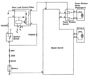
The following circuit illustrates the 1993 Toyota Hilux Pickup Power Window Control System Electrical Circuit Diagram. It is beneficial for both personal use and for mechanics during repairs. Key components include the door lock relay, junction block, power window...
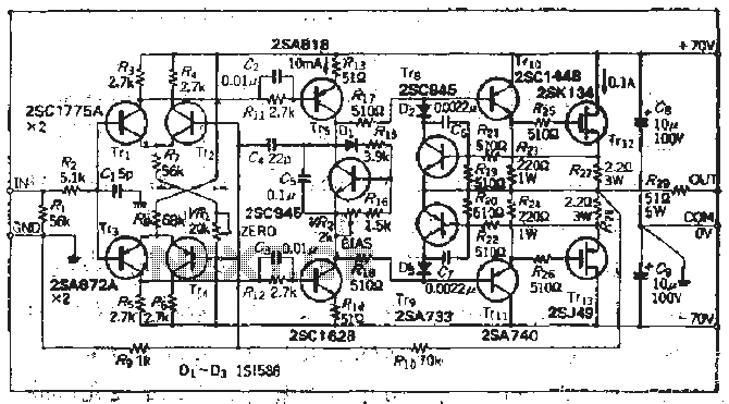
The south circuit consists of four parts, arranged in descending order: an NPN transistor dynamic garbage device (T1), a PNP transistor differential amplifier (T2, T3) forming a double differential circuit, two balanced output amplifiers with opposite phase, and a...
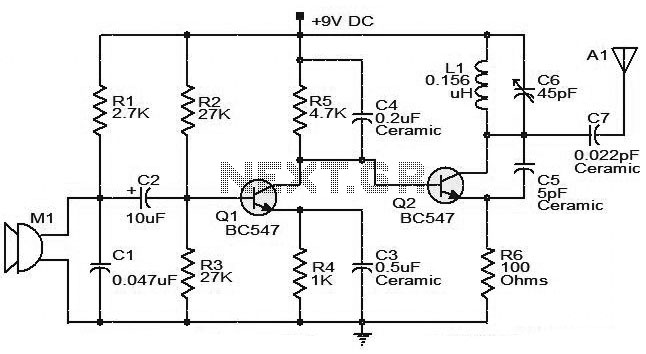
The moderate power FM transmitter circuit employs two transistors. The voice signals picked up by the microphone will be amplified by the transistor. The described FM transmitter circuit utilizes two transistors to facilitate the modulation and amplification of audio signals....
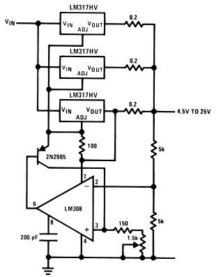
The LM317HV adjustable regulator is capable of supplying more than 1.5A across an output voltage range of 1.2V to 57V. The design of this high-current power supply is straightforward, as the LM317HV requires only a few external resistors to...
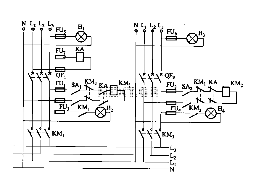
Dual power automatic recovery means one power supply and one standby power supply. When the main power supply is turned off, the standby power supply is automatically activated. Once the main power supply is restored, the system automatically exits...