
Medium power FM Transmitter Circuit With BC547 Transistor

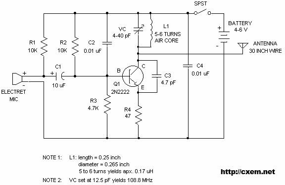
The described FM transmitter circuit utilizes two transistors to facilitate the modulation and amplification of audio signals. The circuit begins with a microphone that captures voice signals, which are then fed into the first transistor configured as a common emitter amplifier. This configuration provides initial amplification of the audio signal, ensuring that it is strong enough for further processing.
The amplified audio signal is then fed into the second transistor, which serves as an oscillator. This transistor is configured to modulate the audio signal onto a carrier frequency, typically within the FM band. The modulation process involves varying the frequency of the carrier wave in accordance with the amplitude of the audio signal, resulting in an FM signal that can be transmitted over the air.
The circuit may include additional components such as resistors and capacitors to stabilize the operation of the transistors and to filter the output signal. An LC tank circuit may also be incorporated to determine the transmission frequency and enhance the quality of the emitted signal. The output of the second transistor is then connected to an antenna, which radiates the modulated signal, allowing it to be received by FM radios within range.
Overall, this moderate power FM transmitter circuit offers a straightforward design for transmitting audio signals wirelessly, making it suitable for various applications, including personal broadcasting and educational demonstrations. Proper attention to component selection and circuit layout is essential for achieving optimal performance and signal clarity.The moderate power FM transmitter circuit employing two transistors.The voice signals picked by the microphone will be amplified by the transistor .. 🔗 External reference
Related Circuits
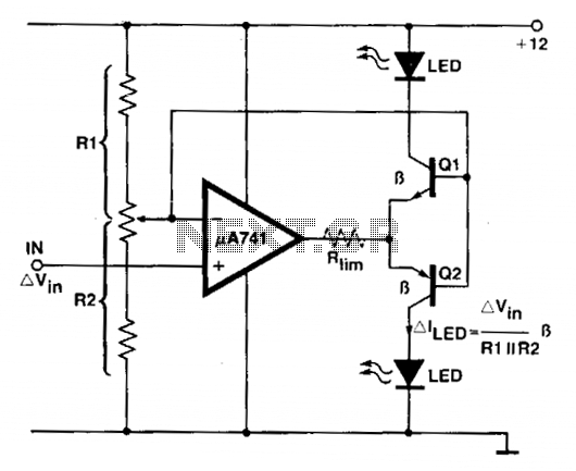
An operational amplifier (op amp) is utilized as a comparator and as a current sink for an LED. The output voltage of the amplifier varies by approximately 1.4 V based on the direction of the current. At any given...
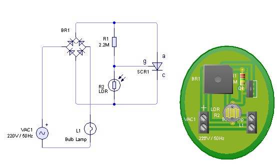
Adjust the value of R1 to achieve optimal performance of the LDR sensor. If, in practice, a resistance of 2.2 MΩ still activates the lamp, it is possible to increase the value of R1 to a larger resistance of...
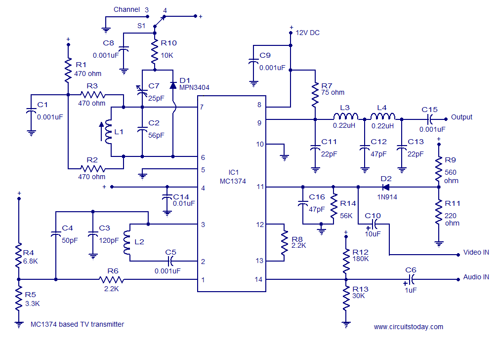
A simple TV transmitter circuit utilizing the TV modulator circuit IC MC1374. It operates with a 12V supply and is capable of broadcasting on channel 3 or 4, employing FM modulation for sound transmission. The TV transmitter circuit based on...
Wireless FM Transmitter. The image displays a wireless FM transmitter alongside a pocket radio and a yellow disk for size comparison. When the user speaks into the transmitter, others can hear the transmission on any FM radio. The wireless FM...
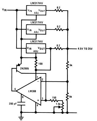
The LM317HV adjustable regulator is capable of supplying over 1.5A across an output voltage range of 1.2V to 57V. The design of this high current power supply is straightforward, as the LM317HV requires only a few external resistors to...
Digital timers feature a clear and precise display. They represent time intervals based on pulse signals, which are decoded by a digital device with a digital display unit. The circuit described pertains to a digital display for these timers,...