
Knight Rider Running Light Schematic

The described circuit utilizes a 555 timer IC configured in astable mode to generate a continuous square wave output, which serves as a clock signal for the CD4017 decade counter. The frequency of the output waveform from the 555 timer can be adjusted by changing the values of the resistors and the capacitor connected to it, thus allowing for control over the speed of the LED animation.
The CD4017 decade counter features ten outputs, each capable of driving a load of up to 20 mA. This makes it suitable for driving standard 5mm or 3mm LEDs, provided that a current-limiting resistor is placed in series with each LED to prevent excessive current flow, which could damage the LED. The typical value for the current-limiting resistor is 220 ohms, as noted in the circuit description.
In the application of this circuit, the first six outputs of the CD4017 are wired to six LEDs, creating a sequential lighting effect that can be visually appealing. When the clock signal from the 555 timer rises, the first output activates, lighting the first LED. As the clock continues to pulse, the subsequent outputs activate in sequence, resulting in a "moving" effect across the display.
The remaining four outputs are configured to reverse the direction of the LED sequence, creating a dynamic back-and-forth animation. This cycling of outputs provides a continuous visual effect that can enhance the aesthetic of model cars or other projects. The circuit is relatively simple and can be easily integrated into various designs, making it a popular choice for hobbyists and engineers alike. Proper attention to component specifications and connections will ensure reliable operation and longevity of the circuit.It can be adjusted to give the desired speed for the display. The output of the 555 is directly connected to the input of a CD 4017. The input of the counter is called the CLOCK line (555). The 10 outputs become active, one at a time, on the rising edge of the waveform from the 555. Each output can deliver about 20mA but a LED should not be connected to the output without a current-limiting resistor (220 © in the circuit above). The first 6 outputs of the chip are connected directly to the 6 LEDs and these move across the display. The next 4 outputs move the effect in the opposite direction and the cycle repeats. The animation above shows how the effect appears on the display. Using 6 LEDs, the display can be placed in the front of a model car to give a very realistic effect. 🔗 External reference
Related Circuits
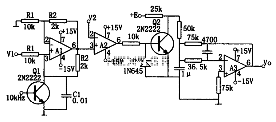
As illustrated in the dividing circuit diagram, A1 consists of a voltage-controlled current source, A2 functions as a voltage comparator, and A3 is configured as an active low-pass filter. When the time constant R1C1 is equal to the clock...
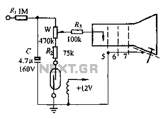
A reed switch is utilized in a TV highlights cancellation circuit. A brightness potentiometer is grounded in series with the reed switch. Under normal operation, the reed contact remains closed, allowing the capacitor C to charge to approximately 160V....
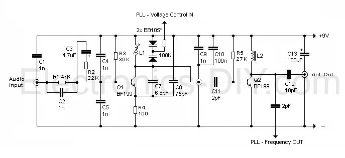
This circuit appears intriguing, and there is an intention to simulate and construct it; however, clarification is needed regarding the meaning of the three symbols in the circuit (one for audio input, one in the middle, and one at...
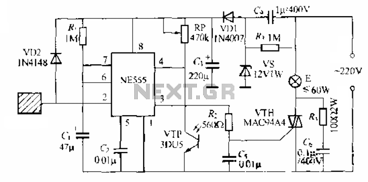
The circuit utilizes a NE553 automatic light sensor composed of 55 groups, allowing lights to turn on when individuals are present and turn off when they leave. The power supply includes VD1, vS, and C, with a 12V DC...
The layout design of the TIQ Flash ADC closely follows the provided circuit diagram. A row layout is implemented, with rows stacked on top of each other. Each row comprises a comparator, a gain booster, a 0-1 generator, and...
This precise one-pulse-per-second clock is constructed using a few common components and is driven by a 50 or 60 Hertz mains supply, without any direct connection to it. It produces a beep or metronome-like click and/or a visible flash...