Knightrider lights for model carss
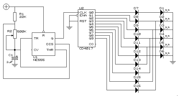
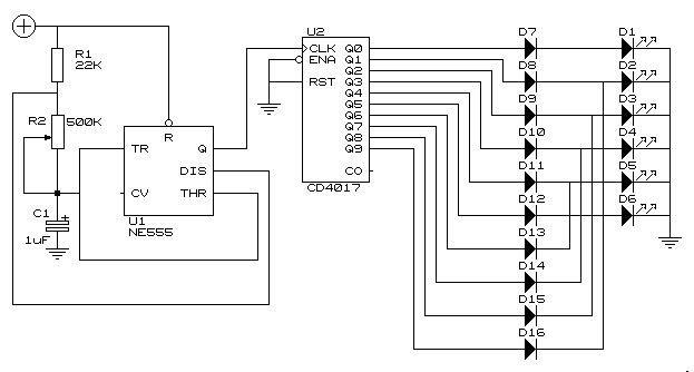
This simple circuit drives six LEDs in a "Knightrider scanner mode." Power consumption primarily depends on the type of LEDs used, particularly when employing a 7555 (555 CMOS version).
The circuit operates by sequentially illuminating the LEDs to create a visual effect reminiscent of the famous "Knightrider" car's scanner light. The configuration typically employs a 555 timer IC, specifically the CMOS variant (7555), which is known for its low power consumption and efficient operation.
In this design, the 555 timer is set up in astable mode, generating a continuous pulse output that drives a series of transistors. These transistors act as switches to control the current flow to each LED. As the timer cycles through its output states, the transistors turn on and off in a sequence, creating the scanning effect as each LED lights up in succession from one end of the array to the other.
The selection of LEDs can significantly affect power consumption; using high-efficiency, low-current LEDs will minimize energy usage while still providing adequate brightness. Resistors may be included in series with each LED to limit current and prevent damage. The values of these resistors should be calculated based on the forward voltage and current specifications of the chosen LEDs.
To enhance this circuit, additional features such as adjustable speed for the scanning effect can be implemented by varying the resistor and capacitor values connected to the 555 timer. This flexibility allows for customization of the visual effect to suit different applications or preferences.
Overall, this simple LED driver circuit is an excellent project for both beginners and experienced electronics enthusiasts, showcasing fundamental principles of timing circuits and LED operation.This simple circuit drives 6 LEDs in `Knightrider scanner mode`. Power consumption depends mainly on the type of LEDs used if you use a 7555 (555 CMOS version). 🔗 External reference
