
Simple 7-Segment Counter Circuit

The 7-segment counter circuit utilizing the CD4033 integrated circuit (IC) is designed to display decimal digits from 0 to 9 on a 7-segment display. The CD4033 is a BCD (Binary-Coded Decimal) counter that can drive a 7-segment display directly, making it an ideal choice for this application.
The circuit typically includes the following components: the CD4033 IC, a 7-segment display, resistors for current limiting, and a clock signal source, which can be generated by a 555 timer or any other clock generator circuit. The CD4033 operates by counting pulses received at its clock input, incrementing the count with each pulse.
The output of the CD4033 is in binary-coded decimal format, which is then decoded to drive the 7-segment display. Each output pin of the CD4033 corresponds to a specific segment of the 7-segment display, allowing the display to represent the counted number visually.
Power supply connections are also essential; the CD4033 requires a DC power supply, typically in the range of 3V to 15V. Proper grounding and bypass capacitors should be included to ensure stable operation.
In summary, the 7-segment counter circuit employing the CD4033 IC is a straightforward yet effective design for visual numerical representation, suitable for various applications such as timers, clocks, and digital counters.The circuit diagram of 7 segment counter circuit has been published here. This circuit consists of counter IC CD 4033 as its central part. 🔗 External reference
Related Circuits
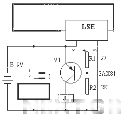
The circuit operation principle of the device illustrated in Figure 13 is as follows: When the barbed wire (Fe) remains intact, the output pin (O) of the LSE is at a high state. Consequently, the transistor (VT) remains off,...
This circuit is utilized for proximity detection and touch-controlled switching. When a finger approaches the sensor, it generates a capacitance to ground with a value ranging from 30 to 100 pF. Components involved include a resistor, capacitor, diode, and...
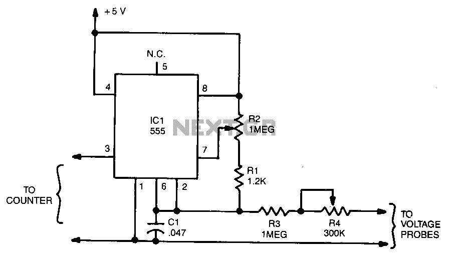
The output frequency from IC pin 3 is determined by the voltage input to pin 6. A standard frequency counter can be used to measure voltages directly over a limited range from 0 to 5 V. In this circuit,...
The output frequency of this simple, low-cost active voltage-controlled oscillator circuit is based on the inherent frequency-dependent characteristics of an operational amplifier. The oscillator circuit utilizes a TL082 op-amp. Upon application of power, the circuit generates a sinusoidal wave....

A high-power and efficient 100W power amplifier electronic project can be designed using the STK404 audio power amplifier hybrid ICs. These ICs consist of optimally designed discrete component power amplifier circuits that have been miniaturized using SANYO's unique insulated...
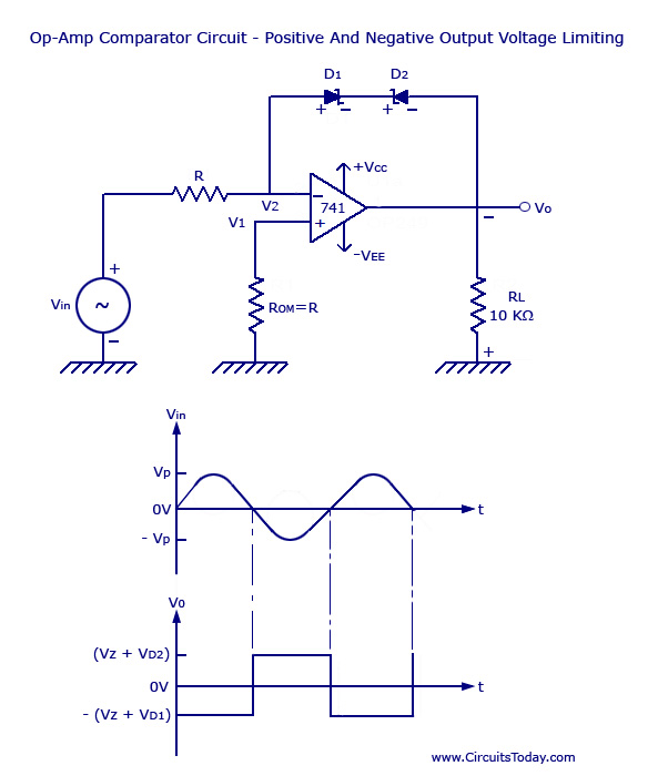
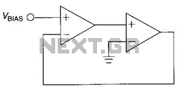
Voltage Limiter Circuit Using Op-amp - Circuit Diagram, Waveform, Positive and Negative Voltage Limiters. The voltage limiter circuit utilizing an operational amplifier (op-amp) serves to restrict the output voltage to predefined levels, effectively preventing it from exceeding or falling below...