
LA3600 5 Band Equalizer Circuit

The audio graphic equalizer using the LA3600 IC is designed to enhance audio playback by allowing users to adjust the amplitude of specific frequency bands. The LA3600 integrates all necessary components into a single chip, making it an efficient choice for audio applications. Each of the five channels corresponds to a specific frequency band, which is predetermined by the circuit design and the values of the capacitors connected to the input of each channel.
The frequency bands targeted by the equalizer are strategically selected to cover the critical range of human hearing, allowing for precise control over bass, midrange, and treble sounds. The lowest frequency of 108 Hz is typically associated with bass sounds, while the highest frequency of 10.8 kHz corresponds to treble sounds. The intermediate frequencies, including 343 Hz, 1.08 kHz, and 3.43 kHz, address the midrange spectrum, which is crucial for vocal clarity and instrument definition.
Adjustments to the center frequencies can be made by altering the capacitance values of the two capacitors connected to each channel. This flexibility allows for customization based on user preference or specific audio requirements. The circuit diagram for the 5-channel audio graphic equalizer with the LA3600 will typically illustrate the connections between the IC, the input audio signal, the output to the amplifier, and the capacitors that set the frequency response for each channel.
In summary, the audio graphic equalizer using the LA3600 provides a user-friendly approach to audio manipulation, allowing for tailored sound experiences across various audio playback scenarios. Its design simplifies implementation while offering sufficient control over key audio frequencies, making it a valuable component in audio engineering and sound system design.One type of regulator of tone / tone controls are the Audio Graphic Equalizer. Audio Graphic Equalizer have 2 kinds in my opinion. Namely Audio Graphic Equalizer Bar and the type of parametric type is often called parametric equalizer. Audio Graphic Equalizer In the article this is the type of bar with 5 channels using IC LA3600. IC LA3600 is a single chip "Audio Graphic Equalizer 5 channel" that is designed specifically for the equalizer five channels. Because IC LA3600 is a special design of the equalizer circuit to make this a simple equalizer. Figure series of Audio Graphic Equalizer 5 channels with IC LA3600 as follows. Audio Graphic Equalizer circuit with IC LA3600 above can control the audio frequencies from 108 Hz to 10. 8 KHz. Audio frequency which is controlled by this equalizer was 108 HZ, 343 Hz, 1. 08 KHz, 3. 43 KHz and 10. 8 KHz. The frequency of that frequency is set based on the value of 2 pieces of capacitors in each chanelnya.
So for instance want to change the center frequency of each channel value of 2 pieces of the capacitor can be changed as desired. 🔗 External reference
Related Circuits
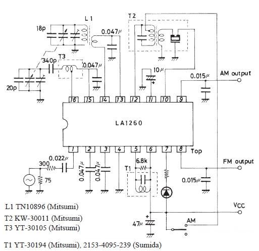
The FM IF MW radio receiver circuit schematic utilizes the LA1260 integrated circuit (IC) for AM and FM radio receiver electronic projects. The LA1260 incorporates numerous functions and features essential for radio receiver applications, including a high signal-to-noise ratio...
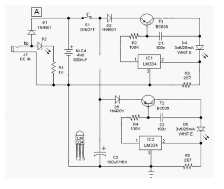
This easy-to-construct "Handy Pen Torch" electronic circuit has a low component count and utilizes two power white LEDs for lighting. It operates on a low voltage supply of 4.8V DC. The Handy Pen Torch circuit is designed to provide a...

This circuit turns off an amplifier or any other device when a low-level audio signal fed to its input is absent for at least 15 minutes. By pressing P1, the device is powered on, supplying power to any appliance...
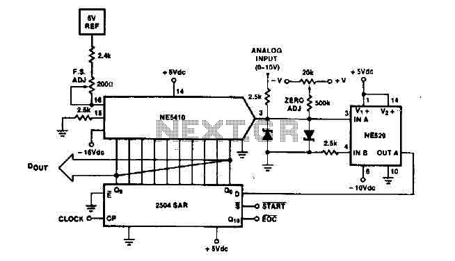
The time IO-bit conversion operates at 3.3 MHz with a clock signal. This converter utilizes a 2504 12-bit register in successive approximation mode, where the conversion signal for the short-cycle end is derived from the first bit utilized in...

This design circuit is for audio graphic equalizers, which are commonly found in commercial products, yet circuits for them are rarely published. The circuit features a simple design that requires an operational amplifier (op-amp) to amplify the input signal....
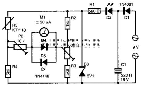
The telephone line tester comprises a meter used to measure line voltage in both the on-hook and off-hook states, three resistors (including one variable resistor), a pushbutton switch, and a modular telephone connector. When the circuit is connected to...