
Circuit Project: A Handy Pen Torch

The Handy Pen Torch circuit is designed to provide a compact and efficient lighting solution using minimal components. The circuit primarily consists of two high-brightness white LEDs that serve as the light source. These LEDs are connected in parallel to ensure even illumination and to maintain brightness even if one LED fails.
The power supply for the circuit is a low-voltage source, specifically designed to operate at 4.8V DC. This voltage can be achieved using four AA batteries in series, which provides a total voltage of 6V. A simple voltage regulator or a resistor can be employed to drop the voltage to the required 4.8V, ensuring the LEDs operate within their specified voltage range for optimal performance.
The circuit's simplicity allows for easy assembly, making it suitable for both beginners and experienced electronics enthusiasts. The low component count not only reduces the overall cost but also minimizes the size of the circuit, making it ideal for portable applications. The Handy Pen Torch can be housed in a lightweight, durable casing, which can be easily integrated into a pen-style body for convenient use.
To enhance the efficiency of the circuit, it is advisable to use current-limiting resistors in series with each LED. This prevents excessive current from flowing through the LEDs, thereby extending their lifespan. The value of the resistors can be calculated using Ohm's law, taking into account the forward voltage drop of the LEDs and the supply voltage.
Overall, the Handy Pen Torch circuit exemplifies a practical and efficient lighting solution, combining ease of construction with effective functionality.This easy to construct “Handy pen torch†electronic circuit and low component count, uses two power white LEDs for lighting. Low volt (4.8V dc) supply ava.. 🔗 External reference
Related Circuits
The crystal-controlled SoftRock receivers developed by Tony Parks (KB9YIG) have played a significant role in introducing many individuals to Software Defined Radio (SDR). For those who prefer not to be limited to a single frequency, the SoftRock Ensemble receivers...
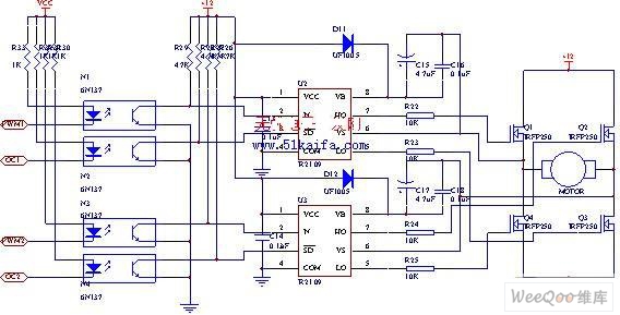
The drive circuit for the electromotor comprises a FET bridge circuit, a FET base drive circuit, a current sensor for the motor drive circuit, and a relay. The FET bridge circuit primarily consists of four high-power MOSFETs, which must...
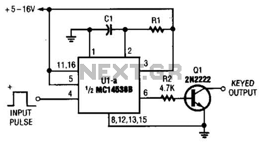
With switch SI in the off position, battery voltage is applied across timing capacitor CI, which remains charged while the rest of the circuitry is powered off. Transistor Q1, and consequently transistors Q2 through Q4, remain in an off...
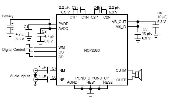
The NCP2830 audio power amplifier features high-quality audio performance with a total harmonic distortion plus noise (THD+N) of 0.04%. It offers low noise with a signal-to-noise ratio (SNR) of up to 100 dB and optimizes overall system efficiency, achieving...
Crystal Y1 generates a fundamental frequency clock signal of 14.31818 MHz. U31 is a Dual Voltage Controlled Oscillator (VCO) that produces a 14.31818 MHz clock signal, referred to as the color clock, at pin 10. The output frequency can...
The amplification of this circuit is approximately 12,000 times, with a bandwidth ranging from 0.5 to 14 MHz. The input resistance is 700 ohms, while the output resistance is 35 ohms (measured at 5 MHz). The output noise level...