
Ladder Tutorial
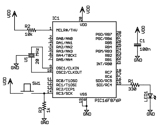
The circuit design utilizes the PIC16F876 microcontroller, which acts as the central processing unit for managing the LED and pushbutton interactions. The microcontroller is programmed to handle three distinct states of the LED: off, steady on, and blinking. The pushbutton serves as the primary input device, configured in an active HIGH arrangement, where pressing the button connects it to Vdd and activates the internal pull-down resistor to ground. This configuration simplifies the circuit design and aligns with modern CMOS technology practices.
The LED's operation is controlled through a circular counter that increments its state with each press of the pushbutton. The states are defined as follows: State 0 corresponds to the LED being off, State 1 corresponds to the LED being steadily on, and State 2 corresponds to the LED blinking. The counter cycles through these states upon each rising edge triggered by the pushbutton input.
In terms of timing, the blinking LED operates at a frequency of 2Hz, achieved by toggling the LED on for 250 milliseconds and off for another 250 milliseconds, resulting in a 50% duty cycle. The circuit includes a three-terminal resonator, which provides the necessary clock signal for the microcontroller. While a crystal oscillator could be used for higher accuracy, the chosen resonator simplifies the design and reduces component count.
The ladder logic program is structured into rungs, with the first rung initializing the LED control. The rung includes a coil that represents the LED, which is energized based on the state of the counter. The second rung employs a TON (Timer On Delay) instruction to manage the timing for the blinking state, while the third rung utilizes comparison instructions to evaluate the current state of the counter and determine the appropriate action for the LED.
Simulation of the ladder logic program is conducted within LDmicro, which allows for real-time testing of the circuit's functionality. The simulation environment visually represents the ladder diagram and enables the user to simulate button presses to observe the corresponding changes in the LED's state. This iterative testing process ensures that the program behaves as intended, providing a practical demonstration of the ladder logic programming concepts and the operation of the microcontroller within the circuit.In this tutorial, I will show you how to write a very simple program. I am assuming that you have written ladder logic before, and that you have some basic familiarity with microcontrollers, but that you have never used LDmicro. If you don`t know very much about ladder logic or PLCs, then the plcs. net tutorial might be helpful to you. Our device w ill have one pushbutton, and one LED. At startup, the LED will be off. When you press the pushbutton once, the LED will turn steady on. The second time you press the pushbutton, the LED will start blinking. The third time that you press the button, the LED will turn off again. On subsequent presses, the cycle will repeat. We will be using a PIC16F876, which is easily available from Digikey or other online distributors. It comes in a number of different packages; I chose a DIP. Note that as of Nov 2009, the PIC16F876 is no longer recommended for new design. This means that it will probably get discontinued at some point in the next few years. You may prefer to instead use a PIC16F886, which is pin-compatible. If you do, then make sure to specify the correct part when you compile, since the `F886 is not code-compatible. The microcontroller (IC1) is part number PIC16F876-20I/SP-ND at Digikey. Almost any three-terminal resonator (U1) will do; you might try a 535-9356-ND or an X909-ND. The only thing that might confuse you is that the pushbutton goes to Vdd, and there is a pull-down. You might be more used to seeing a pushbutton to ground with a pull-up. For TTL, this mattered. For modern CMOS it does not, and I find this `active HIGH` arrangement less confusing than the traditional `active LOW` circuit.
Also, I chose to use a ceramic resonator with internal capacitors, U1, instead of a crystal and two ~20pF caps. A crystal would work just as well and it would be more accurate, but it would be a little bit more expensive, and you would need more parts.
This will flash at 1/(250+250)ms), or 2Hz, or twice per second. The duty cycle will be50% ”250ms on, then 250ms off. This circuit can make any kind of oscillator, with whatever period or duty cycle you require, so it is a good one to remember. Also notice that we have chosen to use an internal relay (`Rfoo`) instead of one attached to an I/O pin (`Yfoo` or `Xfoo`).
This makes sense, because there is no particular reason to bring that signal out to a pin. LDmicro will automatically assign memory for the internal relay. Our program will have three states: off, steady on, and blinking. The program should change its state on each rising edge of the signal from the pushbutton. This is a good application for a circular counter. We will say that `state 0` is `off, ` `state 1` is `steady on, ` and `state 2` is `blinking. ` The counter counts 0, 1, 2, 0, 1, 2, . , so if we just let the rung-in condition of the counter be the pushbutton input, then everything will work like we want: | [Cstate =] Yled | 3 |-[ 1 ]-+-( )-| | | | | [Cstate =] Rosc | | |-[ 2 ]-] [-+ | It should be easy to convince yourself that this does what we want. If the program is in state 1, then the `Cstate = 1` instruction energizes `Yled`, as desired. In state 2, the `Cstate = 2` instruction energizes `Yled`, but only when `Rosc` is also true. Since `Rosc` is oscillating, that means that the LED will blink, as desired. Finally, in state 0, neither of the equals instructions will be true, so there is no way that `Yled` could ever turn on.
We want to enter the first rung from the listing above. We will start with the coil, so choose Instruction -> Insert Coil. This will create a coil named `Ynew. ` This is what we want, except that the name is wrong, and it should be negated. Double-click the coil; this will bring up a dialog where we can fill that in: Now we can insert the rest of that rung in the same way. Click on the left edge of the coil, so that the cursor is vertical, and to the left of the coil. Now choose Instruction -> Insert TON (Delayed Turn On). Once again double-click the timer to rename it and set the period. Add the TOF timer and the contacts in the same way. The second rung is easy: just fill in the two instructions in the right order, by placing the cursor where you want to insert and then choosing Instruction -> Insert.
Remember to assign a name (`Xbutton`) to the contacts, and to set the name and upper limit of the counter. Then choose Edit -> Insert Rung After again. Your program should look like this: The third rung will be a bit trickier, because it has parallel branches.
That means that you have to think about the order in which you insert the instructions. First, insert the coil, and rename it: Now insert the first equals instruction to the left of the coil, as usual, and fill in the correct variable name and value. After you do that, add the parallel branch. You can do this by clicking on the bottom edge of the equals instruction; the cursor will be horizontal and below that equals instruction: Now choose Instruction -> Insert EQU (Compare for Equals).
Since your cursor is below the first equals instruction, the new equals instruction will be inserted below that instruction, in parallel with it. Rename it as usual. To finish the rung, you must insert the `Rosc` contacts to the right of the second equals instruction.
To do this, click on the right edge of the second equals instruction: At this point you can choose Instruction -> Insert Contacts; the contacts will be inserted in series with the second equals instruction, as you require. Rename it and you are done: Now we are ready to simulate our circuit. Choose Simulate -> Simulation Mode. The display will change; the ladder diagram will appear mostly greyed, but you won`t see anything changing with time.
That is because the PLC is not yet cycling. To start it cycling, choose Simulate -> Start Real-Time Simulation. Now you will see things happening: the oscillator is obviously running, but the LED (`Yled`) is still off, which is what we want, because no one has pressed the button yet. To simulate pressing the button, double-click the text `Xbutton` in the list at the bottom of the screen.
You have now simulated bringing the pushbutton input high; this is what would happen if someone depressed (but did not yet release) the pushbutton. You can see that the program is working: the `Cstate` counter is now equal to 1, which corresponds to the `steady on` state, which is what we want.
The LED output is high; you can see that its value is 1 in the list, and the `Yled` coil appears red on the diagram. Double-click the `Xbutton` text in the list to simulate releasing the button, then double-click it again to simulate pressing it again; the `Yled` coil will start blinking, as designed.
If you simulate a third button press then the output will go steady low. So now we are . 🔗 External reference
Related Circuits
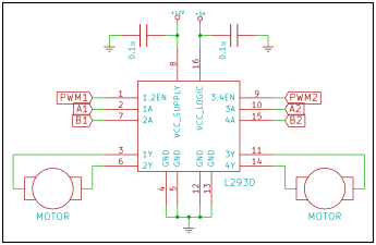
The H-bridge is a circuit utilized in the electronic control of high-current devices, particularly in applications where the device's polarity needs to be reversed, such as in DC motors. The name derives from the circuit's resemblance to the letter...
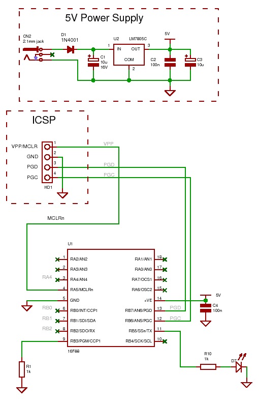
For the other components, most of the necessary items should be available if any type of electronics work has been done, except for the programmer, RS232 chip, and PIC. To transfer information from the project to the PC, a...

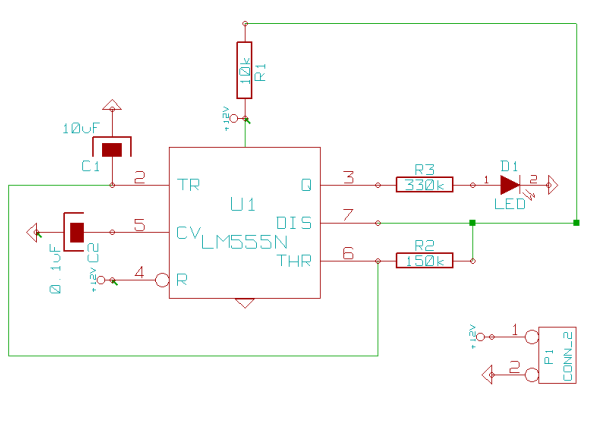
Portable Jacob's Ladder circuit designed specifically for experimental purposes. The Portable Jacob's Ladder circuit is an intriguing project that demonstrates the principles of high-voltage arc generation. This circuit is typically utilized in educational settings or experimental demonstrations, showcasing the behavior...
This page outlines how to create a simple theft deterrent that can be quite effective. The concept involves using a flashing red LED to indicate that the vehicle is protected. This device serves to safeguard the car from potential...
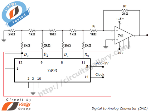
A Digital to Analog Converter (DAC) is utilized to produce an analog voltage that corresponds to input digital data. Binary data can be transformed into its analog equivalent using an R-2R ladder network combined with a summing amplifier, which...
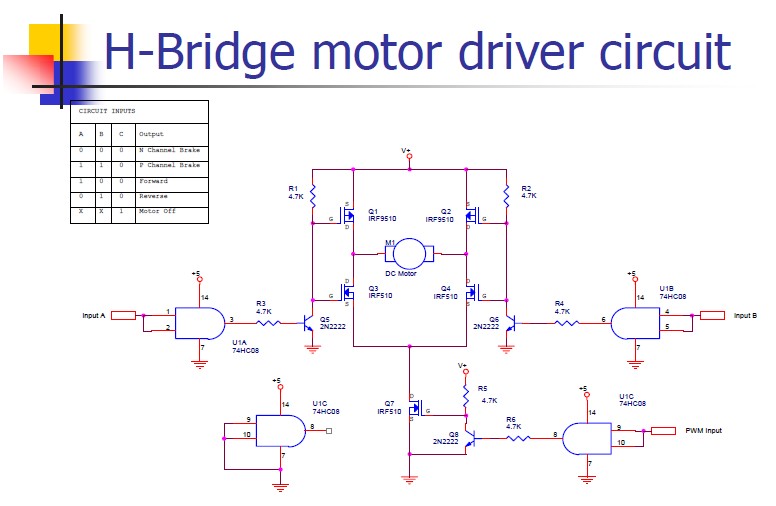
An H-bridge motor driver circuit is designed to control a DC motor. By using a low signal, such as a 5-volt signal, the circuit enables the program to manage the motor, which operates on a higher power supply. The H-bridge...