
robot tutorial dc motor control system

The H-bridge motor driver circuit is a fundamental component in motor control applications, particularly for DC motors. It allows for bidirectional control of the motor by enabling current to flow in either direction through the motor windings. The circuit typically consists of four switches, which can be implemented using transistors or MOSFETs. These switches are arranged in an H configuration, hence the name "H-bridge."
When a low control signal is applied to the H-bridge, it activates specific switches to allow current flow in one direction, causing the motor to spin in one direction. Conversely, reversing the control signals activates the opposite switches, allowing current to flow in the opposite direction and reversing the motor's rotation. This functionality is crucial for applications requiring precise control over motor direction and speed.
The use of a low voltage control signal, such as 5 volts, is advantageous as it allows microcontrollers or other low-power devices to interface with high-power motor systems without the need for complex and bulky control circuitry. The H-bridge can also incorporate features such as PWM (Pulse Width Modulation) for speed control, enabling fine-tuning of the motor's performance.
In practical implementations, additional components such as diodes may be included to protect the circuit from back EMF generated by the motor during operation. Heat sinks or thermal management strategies may also be necessary to dissipate heat generated by the power devices in the H-bridge, ensuring reliable operation under load conditions.
Overall, the H-bridge motor driver circuit is essential for efficient and effective control of DC motors in various applications, ranging from robotics to industrial automation.H-bridge motor driver circuit to drive the DC motor, so that with low signal (say 5 volt signal), the program will able to control the motor which use high power supply. 🔗 External reference
Related Circuits
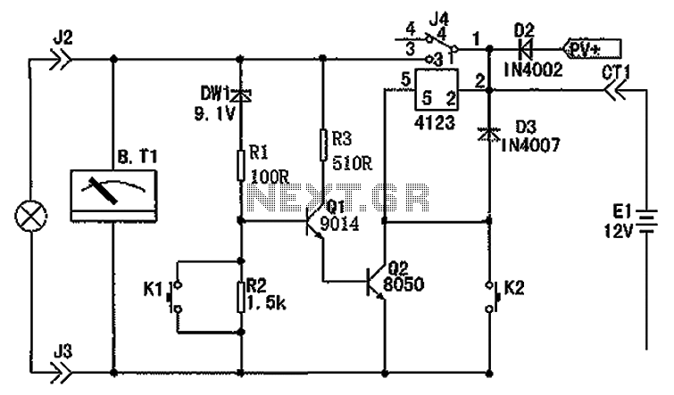
The circuit depicted in the figure consists of a battery, a controller, and various electrical and charging components. It includes a Zener diode (D1) and resistors (R1, R2) for undervoltage detection. The circuit also features transistors (Q1, Q2), resistors...
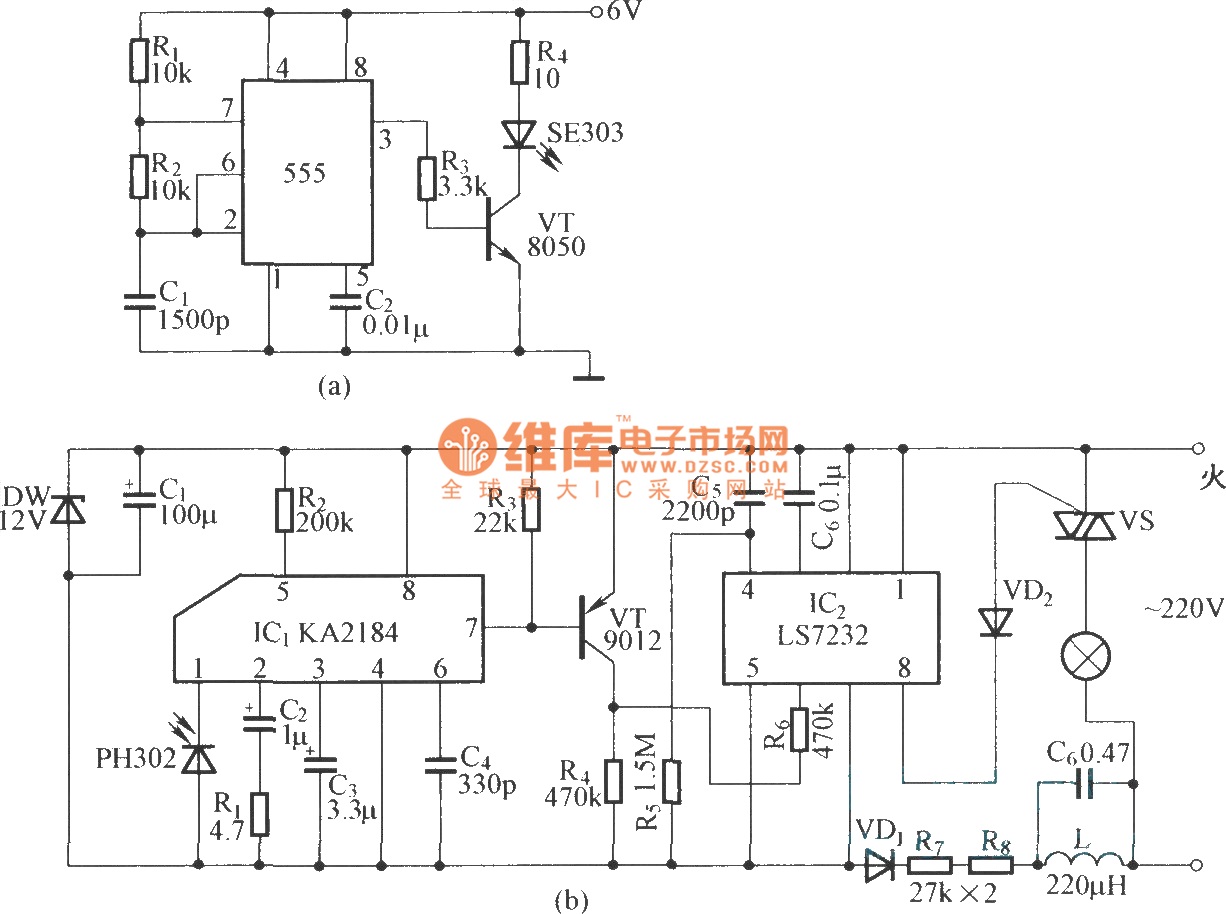
This is an infrared emission circuit diagram. The NE555 circuit generates a 40 kHz pulse, which is sent by the infrared emission control SE303 after being amplified by VT. The remote receiver and infrared dimming circuit are composed of...

This is a BTL (bridged tied load) mono amplifier with a DC volume control circuit. This circuit utilizes the TDA7052A/AT, which is suitable for monitors, TVs, and battery-operated portable radios and recorders. Unlike conventional DC volume circuits, the TDA7052A/AT...
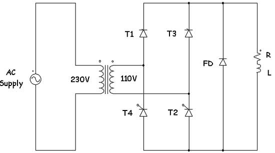
Controlled rectifiers are line-commutated AC to DC power converters that convert a fixed voltage and fixed frequency AC power supply into a variable DC output voltage. The input supply provided to a controlled rectifier is an AC supply with...
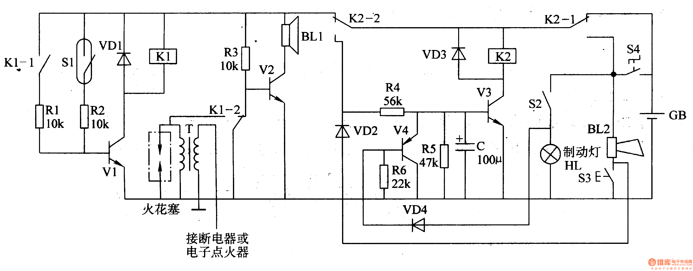
The circuit comprises a trigger circuit, an alarm control circuit, and a reset circuit for the alarm. The trigger circuit includes mercury switches (S1), a resistor, transistors (V1), and a relay (K1). The alarm control circuit is made up...
The remote control robot circuit is illustrated in the accompanying figure. Figure 2-36(a) presents the circuit diagram, while figure 2-36(b) depicts the operating timing diagram. The robot's rotation process involves an ultrasonic launching circuit, which consists of a 40...