
Baby watch Intercom Circuit

This circuit serves as a basic audio monitoring system, suitable for applications such as baby monitoring or intercom systems. It utilizes an electret microphone (M1) as the primary audio input, which converts sound waves into electrical signals. The gain of the circuit is adjustable through resistor R1, which can be replaced with a trimmer potentiometer for fine-tuning.
The circuit is powered by a 9V battery, ensuring portability and ease of use. It incorporates a relay (RL1) that activates during power interruptions to switch to battery operation, ensuring continuous functionality. The design is efficient, with a low current consumption of approximately 30 mA, making it suitable for prolonged use without frequent battery replacement.
The output stage of the circuit utilizes transistors Q1 (BD139) and Q2 (BD140), which operate in Class B mode. This configuration allows for efficient amplification of the audio signal without the need for a heatsink, as the power dissipation is minimal. The circuit can drive an 8-ohm loudspeaker rated at 0.4W, providing adequate sound output for monitoring purposes.
The passive components in the circuit include various resistors (R1 to R15), capacitors (C1 to C12), and diodes (D1 to D5) that work together to filter, stabilize, and regulate the audio signal. The use of a TL072 operational amplifier (IC1) enhances the audio processing capabilities, ensuring high fidelity in sound reproduction.
The complete part list includes:
- Resistors: R1 (15K), R2-R4 (1K), R3-R7 (1K), R5 (220K), R6 (1M), R8-R9 (1M), R10-R11 (47Ω), R12-R14 (10K), R13 (1K), R15 (2.2K)
- Capacitors: C1 (22μF/25V), C2-C3-C6 (100nF/100V MKT), C4-C9 (1μF/25V), C5-C8 (100pF/100V), C7-C10 (470μF/25V), C11 (100nF/100V MKT), C12 (1000μF/25V)
- Transistors: Q1 (BD139), Q2 (BD140)
- Operational Amplifier: IC1 (TL072)
- Fuse: F1 (0.1A)
- Transformer: TR1 (220Vac/9V, 0.2A)
- Microphone: M1 (Electret condenser microphone)
- Switch: S1 (2X2 1A)
- Relay: RL1 (Small relay 12V DC)
- Battery: BATT (9V battery)
- LED: LD1 (3mm RED LED)
This circuit is designed with simplicity and functionality in mind, making it an ideal choice for basic audio monitoring applications.It's a very simple circuit, for the follow-up of baby. It can however be also used for other use, as intercom etc. In the place of M1 we can we use a simple electret mic capsule. The regulation of gain becomes from the R1, whoever can be trimmer or potesometer. Has been added also a small automatism, round the RL1 and battery 9V for the case where we have interruption of AC Line. The life of battery is enough big, one and the consumption of current is small, roughly 30 mA, for loudspeaker 8R /0,4W.
The transistors do not need heatsink, one and work in Class B. Part List R1=15Kohms C1=22uF/25V Q1=BD139 R2-4=1Kohms C2-3-6=100nF/100V MKT Q2=BD140 R3-7=1Kohms C4-9=1uF/25V IC1=TL072 R5=220Kohms C5-8=100pF/100V F1=Fuse 0,1A R6=1Mohms C7-10=470uF/25V P1=470kohms Trimmer or potesiometer R8-9=1Mohms C11=100nF/100V MKT TR1=220Vac/9V 0,2A Transformer R10-11=47ohms C12=1000?F/25V M1=Electret condenset Microphone R12-14=10Kohms D1-5=1N4002 S1=2X2 1A SW R13=1Kohms LD1=Led 3mm RED BATT=9V Battery R15=2.2Kohms RL1=Small RELAY 12V DC 🔗 External reference
Related Circuits
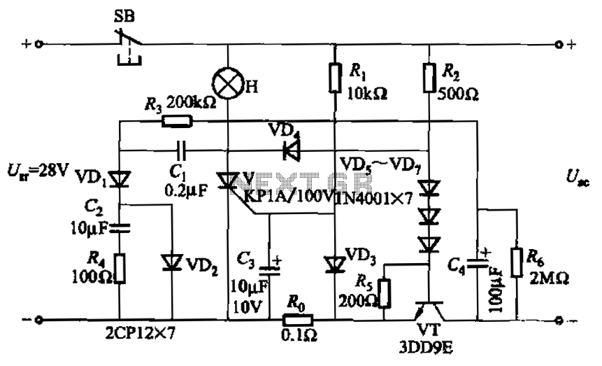
Capacitor C3 is used to determine the cutoff power, specifically the voltage threshold (VT cutoff), which influences the delay time selection. The schematic includes a reset button, SB, that is utilized to reset the system after a failure has...
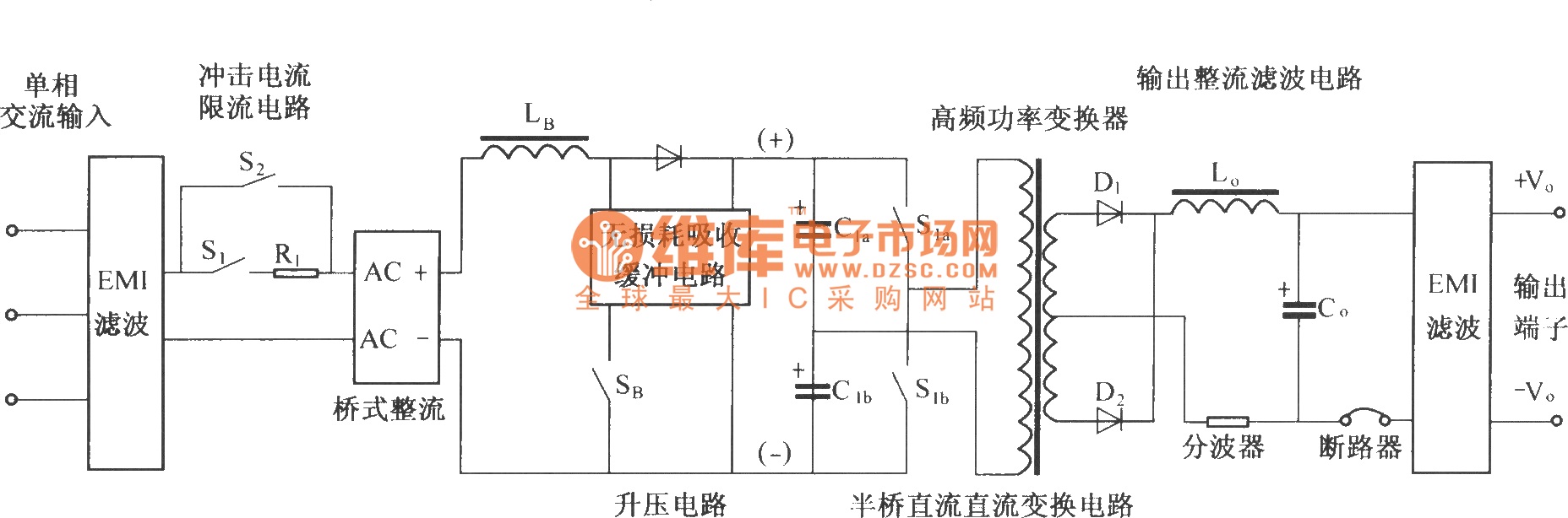
The figure illustrates a simplified schematic diagram of the main circuit DMA12. It primarily consists of the input circuit, an electromagnetic interference (EMI) filter circuit, an impulse current limit circuit, an input rectifier filter circuit, a boost/power factor correction...
KA2211 is a dual audio power amplifier intended for consumer applications. It is designed to deliver high power with low dissipation and low noise. Additionally, it includes various protective features and is suitable for high-performance car audio applications. The KA2211...
The TBA120 Series integrated circuits (ICs) offer a high-gain limiting intermediate frequency (IF) amplifier and a quadrature coincidence detector in a single package. These ICs are primarily designed for the extraction of television intercarrier sound, which is frequency modulated...
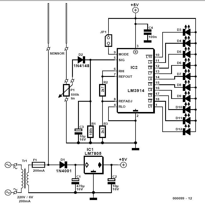
For individuals who prefer not to engage directly with soil, this simple soil moisture tester efficiently assesses the condition of their plants and the level of care they require. The soil moisture tester is a device designed to measure the...
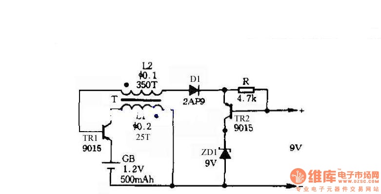
The circuit does not require a separate power switch or transformation to control the switches on the table. It offers advantages such as low power consumption, stability, reliability, and no impact on instrument accuracy. The transformer T in the...