
lan tester circuit

This LAN tester circuit, as designed by Vassilis Stergiopoulos, is versatile and can be implemented in two distinct configurations. The first configuration leverages the timer IC555 in conjunction with the decade counter 4017, facilitating a straightforward approach for testing LAN connections. The IC555 timer operates in astable mode to generate pulse signals, while the 4017 decade counter sequentially counts these pulses, providing a visual indication of the connection status through LEDs or other output devices.
The second configuration employs the ATtiny2313 microcontroller, offering a more advanced and programmable solution. This design allows for enhanced functionality, such as customizable testing protocols and the ability to interface with other digital components. The microcontroller can be programmed to display results on an LCD or transmit data to a computer for further analysis.
The DC battery tester circuit designed by Matthew B. serves a practical purpose in measuring voltages across a range from 1.5V to 9V. Utilizing a straightforward resistor network, the circuit can accurately assess battery health and provide a visual representation of the voltage level through the panel meter. The inclusion of specific resistor values ensures that the circuit operates within safe parameters, preventing damage to the meter or the circuit itself.
The remote control tester circuit is particularly useful for troubleshooting infrared remote controls. By incorporating the TSOP1738 infrared receiver module, this circuit detects signals emitted by the remote and provides immediate feedback through an audible tone. This feature simplifies the process of identifying operational issues with remote controls.
The low resistance connection tester utilizes a 741 operational amplifier configured in differential mode. This setup is effective for testing various connections, such as cables and solder joints, by measuring small resistance values. The circuit's design allows for quick identification of faulty connections, which is crucial in maintaining the integrity of electrical systems.
Lastly, the flame, gas, and smoke detector circuit plays a vital role in safety and security systems. By integrating with alarm systems, this circuit can trigger a relay to activate an alarm in the event of a hazardous condition. The schematic and component list provided facilitate easy assembly and implementation of this essential safety device. Security systems utilizing closed loop wiring can benefit from these designs, although considerations for potential tampering must be addressed to ensure system reliability.This LAN tester circuit originally designed by Vassilis Stergiopoulos. This LAN tester circuit optionally has two designs. The first design is built based 2 main ICs that are timer IC555 and decade counter 4017. The second design is based microcontroller chip ATtiny2313 (the other kind of microcontroller should be work). The first design circuit ( 555. Here the circuit diagram of DC battery tester designed by Matthew B. This circuit can be used to measure DC battery from 1. 5V up to 9V. Component Parts List: R1 = 18K Ohm R2 = 240 Ohm R3 = 8. 2K Ohm R4 = 3K Ohm R5 = 10 Ohm M1 = Panel Meter (Anyone will. Here is the remote control tester circuit. This circuit is really a simple and easy tester for verifying the basic operations of an infrared remote control unit. It is low-cost and very easy to construct. The tester is designed around infrared receiver module TSOP1738. Operation of the remote control is identified by a tone from. Here the low resistance connection tester which can be used as cable or wire tester, soldered joints and other types of connection with resistance value between 0.
25 and 4 ohm. Notes This simple circuit uses a 741 op-amp in differential mode as a continuity tester. The voltage difference between the non-inverting and inverting inputs is. Flame, gas and smoke detector for fire alarm. You can combine this circuit with alarm circuit. The output will be the relay which switch on and switch off the alarm. Schematic diagram: The list of components needed: Download include the explanation of the circuit: Download link A Many security systems use a closed loop of wires and switches arranged so that whenever a door or window is opened, the loop will be broken and the alarm will sound. An obvious problem is that someone can tamper with the system, short out the loop, and later on, come back and burglarize the.
🔗 External reference
Related Circuits
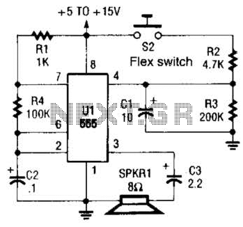
This is a cross-sectional diagram of a flex switch. They can be used as pushbuttons or even position sensors. This schematic diagram shows an oscillator, which is used as an alarm sounder, triggered by a flex switch. The flex switch...
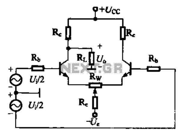
A comparison of four connection methods and features of a differential amplifier circuit is presented. The circuit demonstrates a magnification of a single tube with half the earnings, effectively countering common-mode negative feedback effects. The Common-Mode Rejection Ratio (CMRR)...
This compact video transmitter is highly effective for short-distance video surveillance, operating efficiently up to 100 meters. It can be paired with either a black-and-white or infrared camera module, providing excellent image quality on standard color or black-and-white televisions....
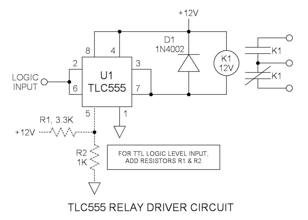
Many integrated circuits possess undocumented features or capabilities. The TLC555 output (pin 3) can sink a load of 100mA down to 1.28V. The open-drain transistor reset (pin 7) can also sink 100mA to 1V. Connecting both lines is permissible...
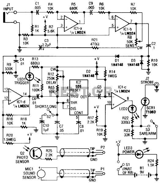
Sound or light sensors connected to J2 produce a voltage that is amplified by IC1-a and IC1-b. A positive trigger voltage developed by D1 and R3, and amplified by IC1-d, drives IC2 and IC1 to trigger SCR1. SCR1 is...

This design presents an innovative approach to the Joule Thief (JT) circuit typically utilized in garden lights. Instead of directly charging a 1.2V battery from the solar cell and converting the power to operate a 3-volt LED, this circuit...