
Alarm Sounder For Flex Switch Circuit

The flex switch is a versatile component widely utilized in various applications, acting as both a pushbutton and a position sensor. The cross-sectional diagram illustrates its construction, which typically includes a flexible substrate, conductive traces, and a sensing mechanism. When pressure is applied to the switch, the conductive traces make contact, completing the circuit and allowing current to flow.
In the schematic, the oscillator serves a crucial role as an alarm sounder. It generates a periodic waveform that can be converted into an audible signal. The oscillator circuit may consist of components such as resistors, capacitors, and an integrated timer or microcontroller, which work together to establish the frequency and amplitude of the sound produced.
When the flex switch is actuated, it triggers the oscillator circuit. This activation can be achieved through various methods, such as direct contact or through an intermediary circuit that amplifies the signal from the switch. The output from the oscillator can be connected to a speaker or buzzer, producing an alarm sound that alerts users to specific conditions or events.
Overall, the integration of a flex switch with an oscillator circuit provides an effective solution for applications requiring tactile input and auditory feedback, such as in alarm systems, user interfaces, and interactive devices. The design considerations for such circuits include ensuring reliable contact closure, optimizing the oscillator parameters for desired sound characteristics, and implementing any necessary protective features to enhance durability and performance. This is a cross-sectional diagram of a flex switch. They can be used as pushbutton or even position sensors. This schematic diagram shows an oscillator, which is used as an alarm sounder, triggered by a flex switch.
Related Circuits
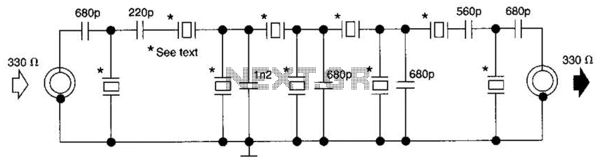
This filter utilizes five 455-kHz ceramic resonators. The impedance is 330 ohms, the bandwidth is 800 Hz, and the ultimate rejection is greater than 60 dB. Additionally, the ceramic resonators can be substituted with crystals. The described filter is a...
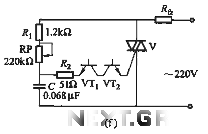
The introduction for a unidirectional thyristor trigger circuit is also applicable to the TRIAC. Various configurations are presented in Figure 16-28. Figures 16-28 (a) and (b) illustrate a direct trigger circuit; Figure 16-28 (c) depicts a dual diode trigger...

Wireless audio and visual transmission to a TV. The TV functions as a receiver, eliminating the need for a separate monitor. It can also be connected to a VCR or CCD camera, enabling the setup of a remote CCTV...

The following circuit illustrates a two-transistor DC motor driver circuit diagram. This circuit utilizes the TIP32 transistor. Features: operates in... The two-transistor DC motor driver circuit is designed to control the operation of a DC motor using two NPN transistors,...

Q1 is an NPN Darlington transistor, and Q2 is a PNP Darlington transistor. MOV1 is a metal-oxide varistor, while R8 is a thermistor used for limiting inrush current. This circuit is designed to limit AC line current to a...

The amplification of this preamplifier is very high. To reduce the amplification, a trimmer resistor R3 in series with a value of 100 ohms should be used. The system can be powered by a voltage ranging from 9 to...