
Photo Strobe Circuit

The circuit consists of several key components that work together to detect sound or light and trigger a strobe light for photographic purposes. The sound or light sensors connected to connector J2 generate an initial voltage signal in response to environmental stimuli. This voltage is then fed into two operational amplifiers, IC1-a and IC1-b, which serve to amplify the signal to a usable level.
The amplified signal is processed further to generate a positive trigger voltage. This is achieved through the diode D1 and resistor R3, which work in conjunction with operational amplifier IC1-d. The role of IC1-d is to further amplify the trigger voltage, ensuring that it is strong enough to drive subsequent components in the circuit.
The output from IC1-d is connected to two additional integrated circuits, IC2 and IC1, which are configured to control the triggering mechanism of the silicon-controlled rectifier (SCR1). SCR1 acts as a switch that controls the power to the strobe light. When the trigger voltage reaches a certain threshold, SCR1 is activated, allowing current to flow to the strobe, thereby producing a flash of light.
This circuit is particularly advantageous for capturing images of dynamic events that are difficult to photograph using conventional methods. The ability to synchronize the strobe with sound or light events enables photographers to capture precise moments, such as impacts or other rapid occurrences, making it a valuable tool in various photographic applications. Sound or light sensors corniected to J2 produce a voltage that is amplified by ICl-a and ICl-b. A positive trigger voltage that is developed by D1 and 1)3 and amplified by ICl-d, drives 1C2 and 1C1 to trigger SCR1. SCR1 is connected to a strobe. This device is handy for photographic purposes to take pictures of events that involve sound, such as impacts, ctc.
Related Circuits
The thermocouple cold junction compensation circuit and the MAX6675 converter circuit diagram form a temperature measuring system. The system utilizes a K-type thermocouple connected to the T terminals of the MAX6675, with the cold junction grounded. An 8051 microcontroller...
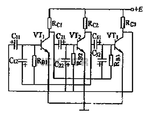
The three astable circuit is illustrated, demonstrating that each level of the transistor's base is connected by a capacitor between the two levels, ensuring tight coupling. Additionally, each base electrode is biased through a resistor (Rb) connected to the...
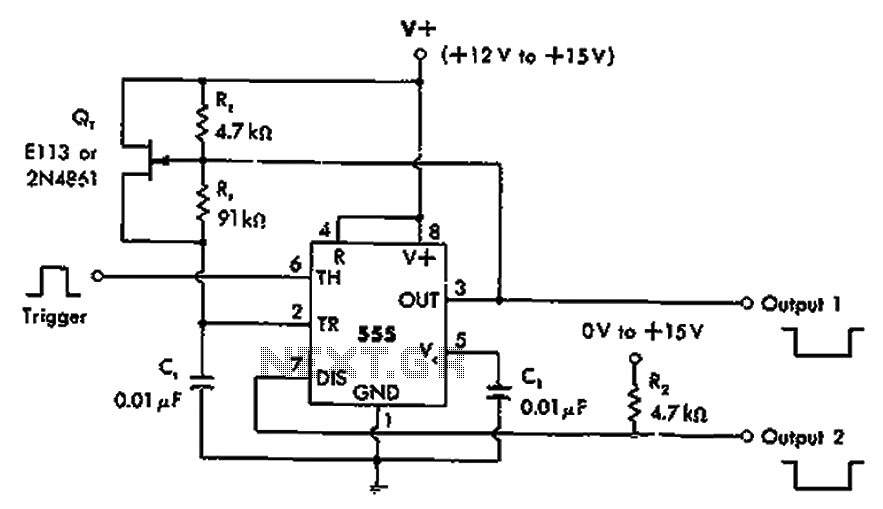
The timer 555 is activated by a positive trigger pulse, which results in negative output pulses. In scenarios where the duty cycle exceeds 99%, heavy loads can be disconnected from pin 7 without impacting timing accuracy, although loads exceeding...
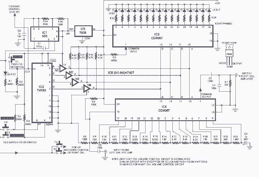
Switch S2 is used for increasing and switch S3 is used for decreasing the volume. Similarly, switches S4 and S5 are provided for second channel (right channel) volume control. Also, pin 14 of IC2 can be connected to IC...
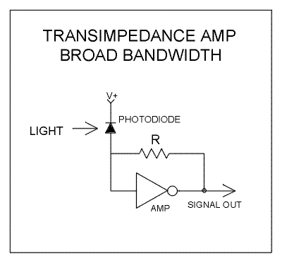
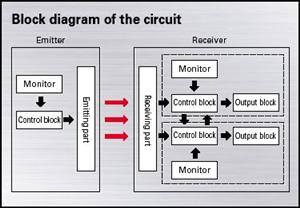
The primary function of the optical receiver is to extract information encoded on a modulated light carrier from a distant transmitter and restore it to its original form. A typical through-the-air communications receiver can be divided into five distinct...
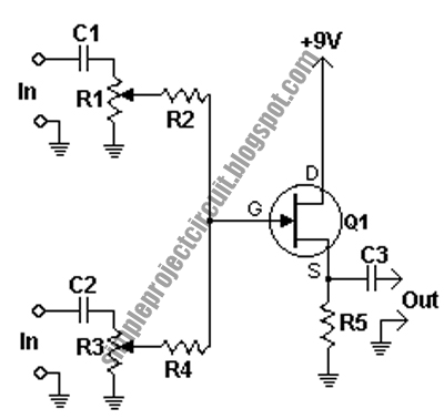
This circuit is a conventional Pierce type oscillator that utilizes a JFET. It operates with fundamental mode crystals and exhibits good performance and reliability when a low noise JFET is employed. The feedback is regulated by the capacitance of...