
Tracking Double-Output Bipolar Supply Circuit

The described circuit functions as a laboratory bench power supply, capable of providing either separate or tracking output voltages. The use of a 24-Vac wall transformer (Tl) serves as the primary power source, delivering the necessary alternating current input for the power supply.
The circuit is designed to incorporate voltage regulators that convert the AC input into a stable DC output. To ensure reliable operation, these regulators must be adequately heatsinked to dissipate the heat generated during voltage regulation, thereby preventing thermal overload and ensuring long-term stability and performance of the circuit.
In separate operation mode, the circuit allows for independent output voltages from each regulator, which can be adjusted to meet specific voltage requirements for various laboratory applications. In tracking operation mode, the outputs are configured to maintain a constant voltage difference, which is particularly useful when powering devices that require a specific voltage ratio.
The design considerations for this circuit include selecting appropriate voltage regulators that can handle the expected load current and ensuring that the transformer has a current rating sufficient to support the combined output of the regulators. Additionally, the layout of the circuit should minimize noise and interference, ensuring clean power delivery for sensitive laboratory equipment.
Overall, this bench supply circuit is versatile and efficient, making it a valuable tool in a laboratory setting for powering a wide range of electronic devices and experiments. This circuit is useful for a bench supply in the lab. Separate or tracking operation is possible. The regulators should be properly heatsinked. Tl is a 24-Vac wall transformer of suitable current capacity.
Related Circuits
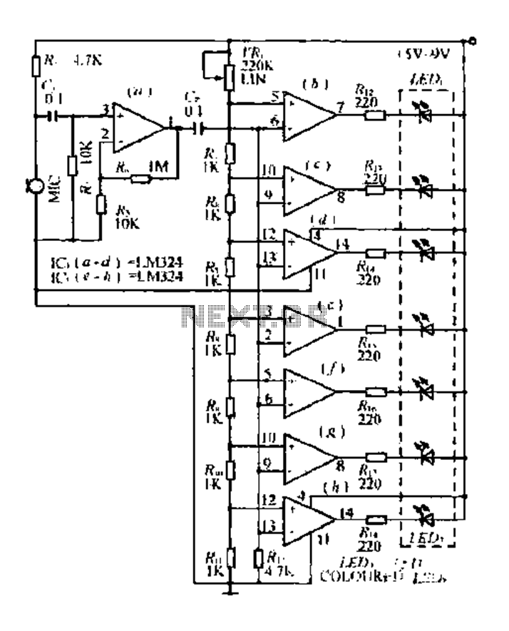
The condenser microphone pickup signal is processed by an integrated circuit (IC) where it is amplified and compared using a comparator circuit. The outputs from the comparators, designated as IC1, IC2, and IC3, provide voltage comparisons based on different...
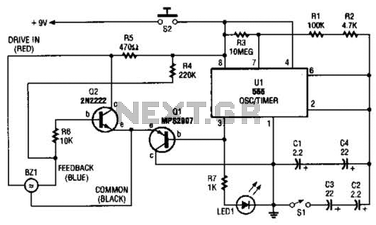
The electronic darkroom timer is constructed using a 555 oscillator/timer, a pair of general-purpose transistors, a buzzer, and an LED. The 555 timer (U1) is set up as an astable multivibrator, functioning as a free-running oscillator. The frequency of...
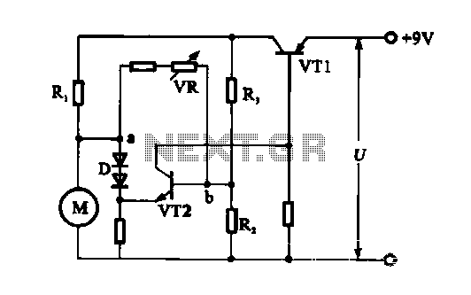
The electronic circuit for steady speed motor applications utilizes an automatic remote control system to regulate the motor power supply, thereby achieving consistent speed control. The circuit diagram illustrates a DC motor connected to the system. Given that the...
The subwoofer is a speaker designed to reproduce low frequencies, specifically in the range of 20 Hz to 150 Hz. The electronic circuit diagram below illustrates the details of a subwoofer amplifier using the TDA1516, a 22-watt amplifier suitable...
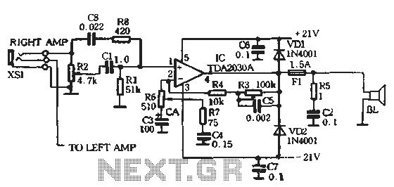
The circuit comprises two main components: the Lisheng power amplifier and the rectifier filter section. The stereo audio power amplifier circuit diagram, depicted in Figure 5-85, illustrates only one channel, with the other channel being identical. The audio signal...
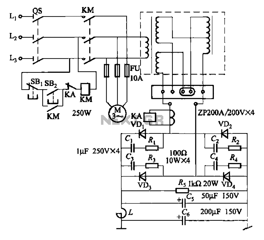
After restructuring the AC and DC arc welding machine circuit on the BX series AC arc welder by installing a rectifier device, it can be converted into an AC and DC arc welding machine. This restructuring results in a...