
Laser Door Alarm Circuit

The laser door alarm circuit consists of several key components that work together to ensure effective operation. The primary component is the laser pointer, which emits a coherent light beam directed towards a photodetector, typically a photodiode or a phototransistor. The photodetector is positioned directly in line with the laser beam and is responsible for detecting any interruption in the light path.
When the laser beam is uninterrupted, the photodetector remains in a state of low conductivity, keeping the output voltage at a stable level, which can be monitored by a microcontroller or a simple comparator circuit. Once an object, such as a person, crosses the beam, the light is blocked, causing the photodetector to switch states. This change can be detected by the circuitry, which then activates an alarm system, such as a buzzer or a siren.
To enhance the functionality of the alarm system, additional components may be included, such as an adjustable resistor to fine-tune the sensitivity of the photodetector, and a relay to control higher power devices. A power supply circuit is also necessary to provide the required voltage for the laser pointer and the alarm components.
The circuit should be designed with considerations for power efficiency and reliability, ensuring that it can operate continuously without failure. Proper housing for the components is also essential to protect them from environmental factors and to ensure the alignment of the laser beam with the photodetector is maintained for optimal performance.This laser door alarm is based on the interruption of Laser beam. A low cost Laser pointer is used as the source of light beam. When somebody breaks the la.. 🔗 External reference
Related Circuits
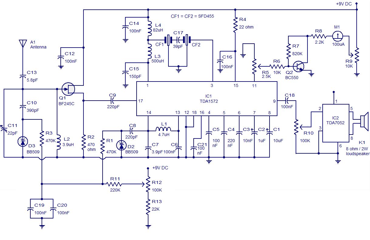
High-quality AM radio circuit based on the TDA1572 IC. The AM radio receiver circuit operates from 9V DC and has a 1W output power. It requires a minimum number of external components. The AM radio circuit utilizing the TDA1572 integrated...
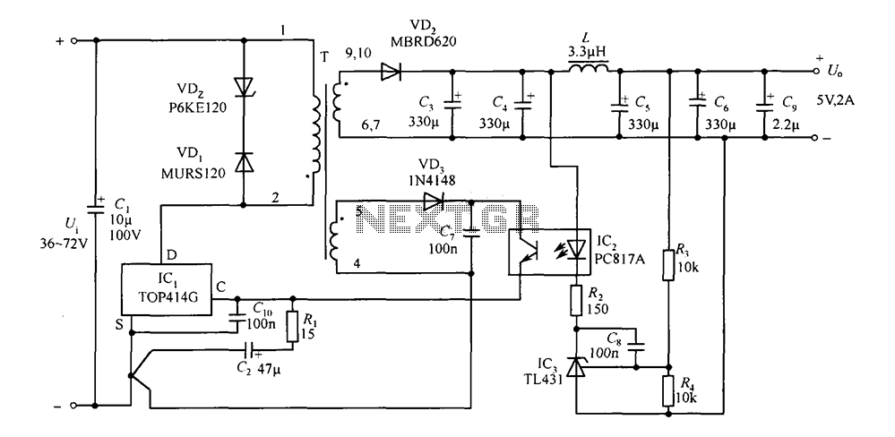
The circuit consists of a 5V TOP414G isolated switching power supply with a 2A output. C1 serves as the input filter capacitor. The circuit includes a voltage clamp protection mechanism composed of VD1. The control terminal is connected to...
The circuit operates in a parallel-fed configuration, as the DC plate current does not pass through the inductor. R3 can be substituted with an RF choke if desired. Capacitor C3 prevents B+ from appearing across the variable capacitor, which...
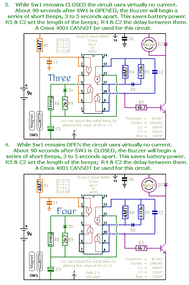
This is a collection of compact, self-sufficient alarm circuits designed for low standby current, making them ideal for battery operation. Some circuits are activated by normally-open and normally-closed switches, while others respond to variations in light or temperature. This...
The Phase-Locked Loop (PLL) will synchronize with an input signal, providing both triangle and square wave outputs. A quad operational amplifier can be utilized in this circuit, making it suitable for audio and low-frequency radio applications. The Phase-Locked Loop (PLL)...
Powered by a solar panel, the circuit provides a 5V pure regulated DC voltage. It consists of an oscillator transistor and a regulator transistor. The solar panel charges the battery when sunlight is sufficient to generate a voltage above...