
Laser Communication (Transmitter

The laser communication system operates by modulating audio signals onto a laser beam, effectively converting sound into light. The transmitter module includes a laser diode that emits a laser beam whose intensity changes according to the audio input. The audio input is conditioned using a potentiometer (VR1) to ensure optimal levels before modulation. The laser beam is directed towards a solar panel, which serves as the receiver. The solar panel converts the light intensity variations back into electrical signals, which are then amplified by the LM386 IC (IC2) and output through a speaker. The design includes various components such as resistors, capacitors, and potentiometers that facilitate signal conditioning, gain adjustment, and stabilization of the system. This circuit is particularly useful for wireless audio transmission in environments where traditional wired connections may not be feasible. Safety precautions must be observed when handling lasers to prevent eye damage.This is the circuit diagram of laser communication system that transmit the sound or music signals by way of a laser beam. The intensity of the laser beam varies together with the amplitude of the sound signal. The variation within the intensity of the laser beam is converted into a variation in the voltage level by utilizing a calculator`s solar
panel. The voltage variation on the solar panel is amplified by a low-voltage audio power amplifier LM386 and reproduced by a speaker. The maximum output of audio amplifier LM386 is 1W, whilst its voltage achieve is 20 to 200. The circuit module consists of a transmitter and also a receiver. Either the transmitter as well as the receiver are assembled around IC LM386, it is powered by a 9V battery.
Take a note that this circuit is different with AV transmitter and AV receiver which can be used for sound and video communication, this laser communication circuit only work for audio/sound transmission. A laser diode (LD1) with maximum operating voltage of about 2. 6V DC and maximum operating current of 45 mA is applied to transmit the audio signal. The voltage divider network formed by R2, R3 and VR3 keeps the voltage and also the current for the laser diode in the secured spot.
In place of the laser diode, it is possible to also use a laser pointer. Take out the battery from the laser pointer. Extend two wires from terminals of LD1 and connect them towards the battery terminals of laser pointer. The spring within the laser pointer will be the negative terminal. The output power of the laser pointer is 5 mW. Be careful when doing work with laser, as direct exposure to the laser beam could be hazardous to your eyes.
Point the laser beam to the solar panel. Potmeter VR1 (10-kilo-ohm) is applied to adjust the level of the input audio signal. The audio input (Vin) is taken from the preamplifier output of the music system (CD player, DVD player, etc). Capacitor C2 and preset VR2 are applied to vary the gain of the LM386. The audio signal transmitted by the laser diode (LD1) is received by the calculator`s solar panel and amplified by IC2.
The gain of the amplifier is fixed by capacitor C7. Preset VR4 is utilized to adjust the signal level from the solar panel. This signal is fed to input pin 3 of IC2 via coupling capacitor C5 so that the DC value from the solar panel could be eliminated. The amplified output from IC2 is fed towards the speaker, which plays the music from the CD player linked on the input (Vin) of IC1.
We aim to transmit more information by carrying articles. Please send us an E-mail to wanghuali@hqew. net within 15 days if we are involved in the problems of article content, copyright or other problems. We will delete it soon. 🔗 External reference
Related Circuits
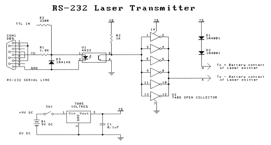
This project is intended for entry-level laser experimenters. The circuit enables communication between two computers with serial (RS-232) capabilities over a distance of 200 meters using a laser beam. A low-cost transmitter-only circuit is also provided for one-way communication...
This is a tutorial, and the creator has experience with making tutorials. The tutorial aims to provide guidance on a specific topic, leveraging the creator's previous experience in producing instructional content. The focus will likely be on delivering clear and...
As before, there are two sections: the transmitter board and the receiver board, both powered by a separate 9V battery or a fixed voltage power supply, depending on your needs. The transmitter board has an electret microphone module at...

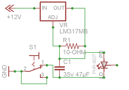
Laser Diode Power Supply. This power supply is designed to provide electricity to consumers at low voltage, specifically 220V. While an external adapter can be utilized, it is not recommended due to size constraints. Therefore, a power supply integrated...
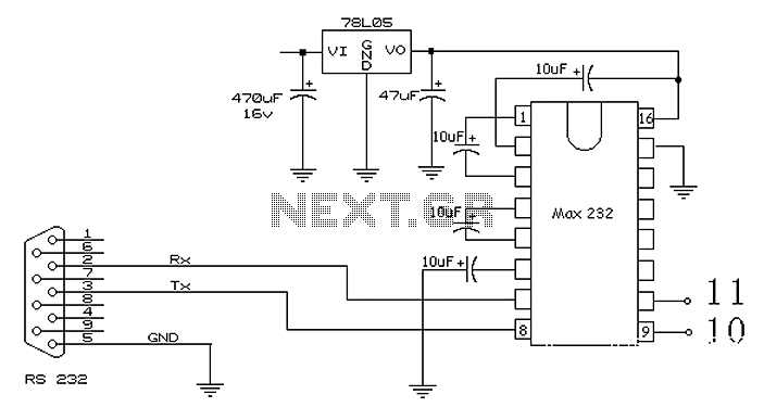
The 51 microcontroller features a full-duplex serial communication port, enabling straightforward serial communication between the microcontroller and a computer. However, certain conditions must be met for effective communication, such as the computer's serial port operating at RS232 levels while...
The motor controller is a custom-built unit that integrates custom printed circuit boards, the Pico Systems Universal Stepper Controller card, Gecko G320 motor drives, and an internal power supply. It also interfaces with servos requiring DC power and motor...