
Laser Head (A2074) Manual
 Manual")
The schematic illustrates that the A2074 provides two independent laser drivers, each with L+ and L- terminals for power and control. There is no shared connection between the two drivers. Laser LD1 activates when the voltage L1 is 7 V or higher, while Laser LD2 activates at L2 voltage levels of 7 V or above. Control voltages should not exceed 15 V for laser currents up to 60 mA, and 10 V for currents up to 150 mA. The circuit can tolerate reverse voltages up to -30 V without damage or activation of the laser. The A2073A and A2051S circuits are designed to switch the lasers of the A2074, with the A2073A specifically controlling LD1.
In the operational setup, five A2074As can be connected to a single A2073A. The A2073A supplies 15 V through a 47-ohm resistor to L1+ and ground through a MOSFET switch to L-. For a current draw of 100 mA from the laser driver, L1 will register 10.3 V, leading to a power dissipation of 430 mW in Q1, which is sustainable indefinitely. For a 160 mA draw, typical for a 65-mW red laser diode, L1 drops to 8 V, resulting in a 300 mW dissipation in Q1.
The capacitor C1 determines the turn-on delay for the laser drive. With a value of 22 nF, the delay is approximately 4 seconds, as demonstrated in the corresponding figure that plots light power against time. The laser power reaches full output (4 mW) after this period. The switching logic pulse from devices like the A2073 and A2051 generates the necessary commands to activate the laser, with a transmission time of 6.8 seconds for each command. The laser activation process begins approximately 4 seconds after the command is issued, reaching full power within 5 seconds. The laser can turn off in about 200 ns, allowing for pulse generation, though the shortest obtainable pulse with this configuration is around 2.5 seconds.
If C1 is set to 47 nF, the turn-on delay increases, risking damage to the laser if the turn-on delay exceeds 6.8 seconds. This is due to potential spikes in power during activation, which can lead to overdrive conditions. Reducing C1 to 22 nF mitigates this spike, preventing damage even after numerous activation cycles. For faster modulation, values as low as 4.7 nF can be used, allowing the laser to turn on within 1 second of the switching pulse. However, lower capacitance values may introduce fluctuations in the optical output power, posing risks to high-power lasers operating near their maximum ratings.
In the event of laser diode failure, the driver circuit attempts to push maximum current through the diode, which may lead to excessive heat dissipation in the components involved. The A2074A, with specific resistor values, can either limit or exacerbate this current flow, impacting component longevity. Proper thermal management and component ratings are crucial to ensure reliable operation under various conditions. The design considerations also include ensuring electrical isolation between the laser can and the chassis, necessitating anodized surfaces and careful assembly practices to prevent short circuits.The Laser Head (A2074) provides drive circuits for one or two laser diodes. The drive circuits provide fast switching from off to full power, while at the same time providing complete protection of the laser diode from over-drive. We turn on the lasers by applying 7 V across the L+ and L ’ terminals of the drive circuit. The circuit monitors the laser`s photodiode current and raises the laser diode current until the photodiode current reaches a level set by its photocurrent resistor. The lasers used with the A2074 must be housed in a three-pin package with the cathode of the laser diode and the anode of the photodiode connected in common to the case (see drawing ).
Examples of such lasers are the LDP65001E (Lumex, now obsolete), the DL3147 (Sanyo), the L650P007 (Thorlabs), the L658P040 (Thorlabs), or the HL6364DG (Opnext). These are all red laser diodes. Their power outputs range from 5 mW to 65 mW, operating currents fom 35 mA to 150 mA, and forward voltages from 2.
0 V and 2. 7 V. The A2074 is also suitable for driving infra-red laser diodes, and even green diode-pumped laser, such as the DJ532-10 (from Thorlabs). But we have not tested the A2074 with either infra-red or green diodes. In principle, the A2074 could drive a blue laser diode, but we have not found one with the correct internal connections for compatibility with the A2074.
In the figure above, the photocurrent resistor, R6 is 15 k ©, which sets the output power of the LDP65001E laser diode on the other side to 4. 0 mW. Note the orientation of the six-way flex connector. The contacts of the flex cable must face away from the board edge. The six-way 1-mm flex socket on the A2074 has a pin-out compatible with switching circuits such as the Azimuthal BCAM Head ( A2048 ), the Azimuthal Source Head ( A2051S ), and the Five-Way Injector Head ( A2074A ).
The following versions of the A2074 exist. Here is an A2074A shown attached to a focusing light injector assembly. Two lenses focus the laser light onto the tip of an optical fiber, which we adjust with a micrometer stage and then glue in place. The metal piece into which the A2074A is screwed must be anodized so as to isolate the laser can from the local ground.
The A3073A used 10 © for R7. The A3073B uses 22 ©, which reduces intensity overshoot at turn-on for our newer lasers, and protects the circuit against over-heating in the case of laser failure. [22-DEC-11] The A2074 provides two independent laser drivers, as shown in the schematic. Each driver has two terminals, L+ and L ’ that provide power and control. There is no common connection between the two drivers. Laser LD1 turns on when voltage L1 is 7 V or higher. Laser LD2 turns on when L2 is 7 V or higher. Neither control voltage should exceed 15 V for laser currents up to 60 mA, or 10 V for laser currents up to 150 mA.
Reverse voltages up to ’30 V cause no damage to the circuit and do not turn on the laser. Circuits like the Five-Way Injector Head ( A2073A ) and Azimuthal Source Head ( A2051S ) LWDAQ devices designed to switch the lasers of an A2074. The A2073A switches only LD1, the first laser diode, which is all that is provided by the A2074A. These two circuits were designed to operate together: five A2074As are attached to a single A2073A. The A2073A connects 15 V through a single 47- © resistor to L1+ and 0 V through a MOSFET switch to L ’.
With the laser driver circuit drawing 100 mA, L1 will be 10. 3 V, which means Q1 will dissipate 430 mW, which it can do indefinitely. If the laser driver draws 160 mA, which is what we would expect for a 65-mW red laser diode drawing 150 mA, L1 will drop to 8 V and Q1 will dissipate 300 mW. Capacitor C1 determines the turn-on delay for the laser drive. With C1 set to 22 nF the delay is 4 s, as we can see in the following figure, in which we switch an LDP65001E laser from 0 mW to 4 mW.
Figure: Light Power versus Time. Full power is 4 mW. We have C1 = 22 nF. The bottom trace is the switching logic pulse. The top trace is the voltage across a 1-k © resistor in series with a 10-mm square phototiode. The laser diode is pressed up against the phototdiode. The photodiode efficiency at the 650-nm wavelength of the laser is 0. 4 A/W. Device like the A2073 and A2051 generate their switching logic pulse response to LWDAQ commands. A LWDAQ command takes 6. 8 s to transmit. We must use one to turn on a laser and another to turn it off, so the switching signal will be at least 6. 8 s long. In the figure above, we see the laser starting to turn on 4 s after the switching signal is asserted, and reaching full power 5 s after.
The laser turns off in 200 ns. The shortest light pulse we can obtain with this 4-mW laser is around 2. 5 s. If we set C1 to 47 nF, the turn-on is further delayed. We hoped to use a delayed turn-on to create tiny pulses like this one, but it turns out that increasing the turn-on delay beyond 6. 8 s endangers the laser. In the following figure we see a 6. 8- s turn-off period. The laser power drops to zero within 1 s, but when we turn on the A2074 again, we see a spike in laser power before the proper turn-on.
Figure: Light Power versus Time. Full power is 4 mW. We have C1 = 47 nF and a LDP65001E laser. The spike is the result of turning on power before C1 has fully discharged after the previous turn-off. It is this spike that damages lasers. During this spike, the A2074 feedback loop over-drives the laser for a few hundred nanoseconds. Our light sensor is not fast enough to detect the over-drive, but we are confident it occurs, because we destroyed half a dozen lasers with a few hundred thousand 6.
8- s off-periods when C1 was 47 ns. When we drop C1 to 22 nF, the spike goes away and millions of short off-periods do not damage the lasers. If we wanted to modulate laser power from fully off to fully on more quickly, the circuit is stable with C1 as low as 4.
7 nF, in which case the laser turns on within 1 s of the switching pulse. Lower values of C1 create more bounce in the optical output power, and so endanger high-power lasers operating near their maximum operating power. Higher-power lasers require more current from the laser driver, and the time to full power is longer.
The following figure shows the A2074A switching an L658P040 laser from 0 mW to 40 mW. Figure: Light Power versus Time. Full-power is 40 mW. We have C1 = 22 nF and an L658P040 laser. The photodiode resistor is 1. 0 k © and photodiode sensitivity is 0. 4 A/W. The turn-on begins 4 s after the switching signal, but the laser does not reach full power until 9 s after. The laser does, however, turn off within 200 ns. For a detailed description of the principles of this laser driver circuit, we refer you to our description of the near-identical laser driver circuit in the Azimuthal BCAM Side Head ( A2049 ).
[11-MAR-13] We load an L650P007, 7-mW laser into the first laser driver of an A3026A, which uses the exact same laser driver as the A2073. We set R6 to 12 k ©. We get 6 mW average optical power, as measured by our SD445 photodiode. We look at the light output versus time during light pulses, and obtain the following trace. We see the overshoot is greatly reduced. We now try an L658P040, 40-mW laser, and set R6 to 68 k © for 6 mW average power. We turn on the laser repeatedly and observe the following traces. The overshoot is small at turn-on. We see a spike during the subsequent turn-on, when we allow only 7 s between pulses. But we see no damage to the laser after several million pulses, so we assume this spike does not over-drive the laser.
The blurring of the intensity trace is an oscillation at 130 MHz in the laser current and light output. The the current through R7 oscillates between 40 mA and 50 mA. We now reduce R6 to 12 k ©. Output power increases to 38 mW and the oscillations vanish. When a laser diode fails, it no longer emits light. The laser driver circuit runs as much current as it can through the laser diode in an effort to make it emit light.
In this case, with 15 V applied to the input of the laser driver, we will have 7 V across Q1, and 6 V accors LD1, Q2, and R7. The voltage at the base of Q2 will be 3 V minus the saturation voltage of the right-hand transistor in U1, say 2.
8 V. The voltage on R7 will be 2. 8 V minus the base-emitter trop of Q2, say 2. 0 V. The A2074A has R7 = 10 ©, in which case the current through the laser diode will be 200 mA. The diode itself will drop around 2. 0 V, even though it is damaged. The diode, resistor, and transistor will each dissipate 0. 4 W, which is enough to make them too hot to touch. The resistor will begin to melt the solder holding it to the printed circuit board. It is Q1 that suffers the most, however, with 200 mA and 7 V for a total of 1. 4 W disspation. These FMMT491A transistors are rated at packages are rated at 500 mW. If instead, as in the A2074B, we set R7 = 22 ©, the maximum current through these three components drops to 91 mA, and the power dissipated in R7, Q2, and LD2 drops to 180 mW. The power in Q1 drops to 700 mW, which is too high, but not high enough to damage the component in a matter of minutes, as is the case for 1.
4 W of dissipation. [12-MAR-13] We try out a 40-mW laser with R6 = 68 k © in the A2074A circuit board, with R7 = 10 ©. The layout of the tracks in the A2074A is far simpler than the longer traces of the A3026A. We think perhaps the inductance of these A3026A tracks causes the oscillations. The following trace shows the light versus time. The laser packages are metal and they are used for the anode of the laser diode itself and for the cathode of its photodiode. Thus the metal can must be connected to the laser driver circuit. There must be a direct-current path from the laser can to one of the power supplies in the circuit that provides power to the laser drivers.
If we use the laser driver with any LWDAQ device, the LWDAQ grounding rules prohibit any direct-current connection between the device chassis and the device power supplies. Thus we must ensure that the laser cans are isolated from the chassis. In devices like the BCAM, we provide isolation by means of non-conducting anodization of the chassis surface.
The nominal diameter of the laser can is 3. 55 mm. We use 3. 7-mm diameter holes with 45 ° chamfers on both ends. These holes are snug enough to locate the laser package within ±80 m of their nominal position, and spacious enough to avoid any scratching of the anodized surface by stray fragments of aluminum oxide when we press the laser into the hole. We check every BCAM for a short circuit between the laser can and the chassis after assembly. No fresh BCAM chassis with a 3. 7-mm hole has yet failed the test. 🔗 External reference
Related Circuits
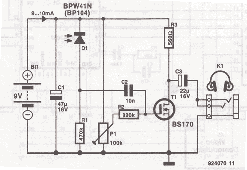
This wireless headphones transmitter ensures quality reception over a distance of 2 meters. The oscillator frequency ranges from 1750 kHz to 3500 kHz, and for the antenna, it... The wireless headphones transmitter operates within a frequency range of 1750 kHz...
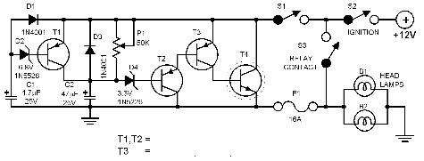
A 1999 Chevrolet Suburban has non-functional headlights. The fuses and circuit breakers have been checked and found to be operational. According to the owner's manual, the headlamps are protected by a circuit breaker located within the lamp switch, but...
Every driver understands that intense light directed at the eyes can lead to hazardous consequences. Vehicles are equipped with a dimmer switch to reduce light intensity; however, some automotive headlamps remain excessively bright even when dimmed. The dimmer circuit...
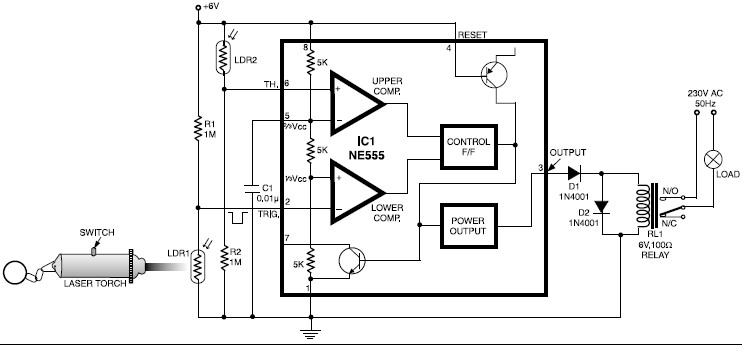
This circuit is designed around a 555 timer and utilizes a minimal number of components. Its simplicity allows even beginners to easily assemble and operate it as a control device. A readily available laser pointer can be used to...
This schematic has been modified from an old Bell & Howell projector amplifier for model 302, utilizing PP 6V6 tubes with a 12AU7 phase inverter (PI). The PI circuit appears to be closest to a "floating paraphase." There is...
The description pertains to a specific type of preamplifiers that are designed to amplify the low output of Moving coil heads, enabling their drive to an input PHONO [RIAA] of a preamplifier. Moving coil heads present certain challenges that require...