
Laser Track Detection

The basic laser pointer circuit consists of several key components that work together to produce a focused beam of light suitable for various applications, including distance detection. The primary component is the laser pointer unit itself, which emits a coherent light beam when powered. This circuit typically includes a power source, a resistor (R1), and the laser pointer.
The power source can be a battery or any suitable DC supply that meets the voltage requirements of the laser pointer. The resistor R1 is critical for limiting the current flowing through the laser pointer to prevent damage. As noted, it is advisable to start with a high resistance value, such as 50 ohms, and adjust based on testing to find the optimal resistance that allows the laser to operate efficiently without overheating.
In applications where the laser pointer is used for detection over long distances, the circuit may also incorporate a photodetector or a photodiode that can sense the laser light. This component will convert the light signal back into an electrical signal, which can then be processed to determine the presence of an object or train within the detection range. The distance and accuracy of detection can be influenced by the alignment of the laser pointer and the photodetector, as well as environmental factors such as ambient light conditions.
For practical implementation, it is essential to ensure that the circuit connections are secure and that the components are rated for the expected operational conditions. Proper testing and calibration should be performed to validate the circuit’s performance in the intended application.The following diagram shows the basic laser pointer circuit. It is identical to the infrared circuit except that the infrared LED`s have been replaced by the laser pointer unit. Due to the long range of these devices this detector method can easily span great distances and could be used to detect trains in a long section of straight track such as in a lader yard or across the throat of a very wide yard.
Laser pointers are not designed for this type of application and careful selection of R1 is required. testing should be carried out to determine the best resistance value for a particular pointer. It is best to start with a high resistance for R1, 50 🔗 External reference
Related Circuits
Thanks to the S6986, the circuit is very simple and requires few components. D2, D3, D5 and D6 forms a bridge rectifier allowing to plug the sensor connector brick in any direction. C1 filters power supply, it must be...
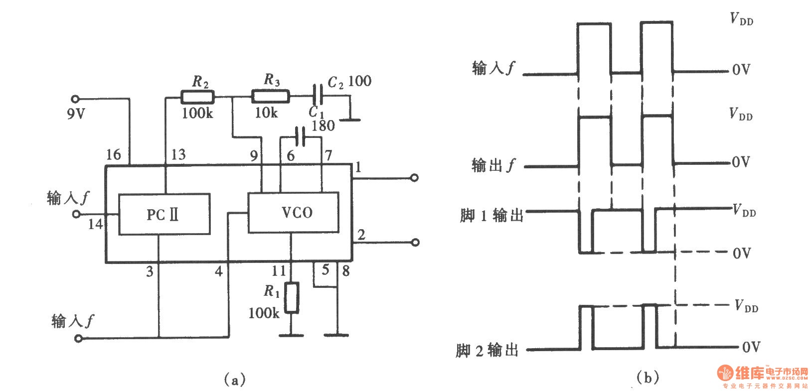
A frequency signal tracking circuit is implemented using a phase-locked loop (PLL) configuration, which is a fundamental application of the CD4046 integrated circuit. The circuit, illustrated in the accompanying chart, utilizes the CD4046 to form a PLL that effectively...
The figure illustrates a simplified representation of the Earth's dipole magnetic field, resembling that of a bar magnet. Field lines originate from the south magnetic pole and terminate at the north magnetic pole. The angle at which this field...
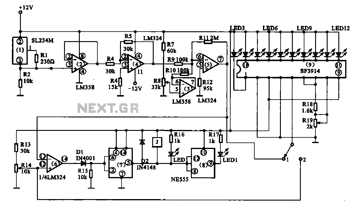
Vegetable greenhouse temperature detection control circuit. The greenhouse temperature detection control circuit is primarily composed of a temperature sensor SL234M, operational amplifiers LM324 and LM358, a dual time base circuit NE555, a relay, and a display driver circuit. The...
The anti-theft system includes two frequency sirens connected to the vehicle's immobilizer system. In the laboratory simulation model, the changes in operating modes, siren activation, and fuel supply cut-off are indicated by the illumination of LEDs and communicated to...
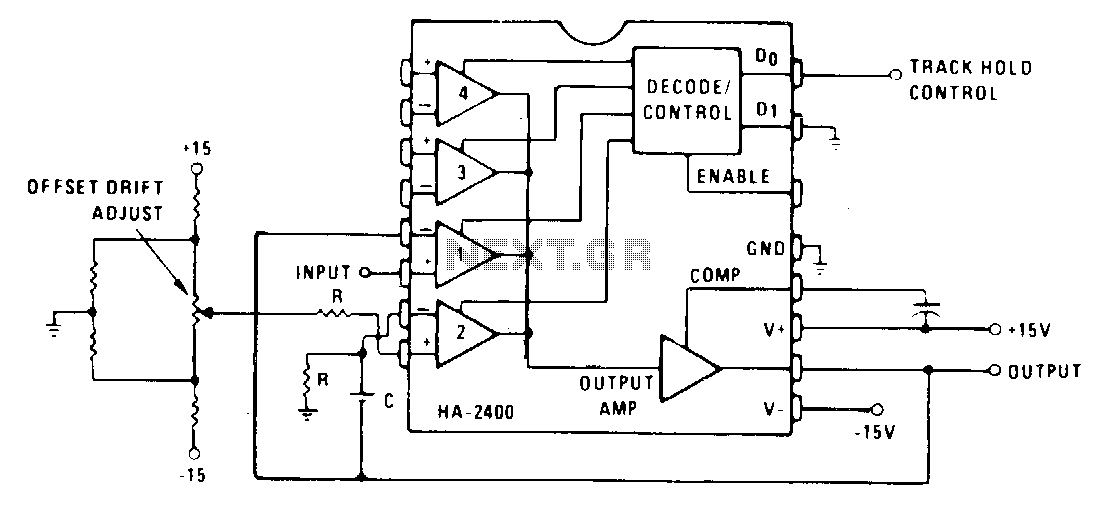
Channel 1 is configured as a voltage follower and is activated during the track/sample time. If the product of R and C is sufficiently short compared to the period of maximum output frequency or sample time, then C will...