
Latching burglar alarm

The described circuit functions as a protective alarm system that activates when the integrity of the circuit is compromised. This system includes a resistor R1, which is part of the voltage sensing mechanism, and a variable resistor R2, which is used for calibration.
Upon interruption of the protective circuit, a signal is generated that triggers an alarm. This alarm serves as a warning mechanism to indicate that the circuit has been opened, which may signify a fault or unauthorized access. The alarm can be an audible signal, such as a buzzer or speaker, that alerts nearby personnel to the condition.
For proper calibration of the circuit, R2 must be adjusted while the protective circuit is open to achieve a voltage of 1 V across R1. This adjustment ensures that the circuit operates within the desired parameters, allowing for accurate detection of any interruptions. The resistance values of R1 and R2 should be selected based on the overall design requirements, including the expected voltage range and the characteristics of the alarm system.
In practical applications, the circuit may also include additional components such as diodes for protection against reverse polarity or transient voltages, capacitors for noise filtering, and possibly a microcontroller for more sophisticated monitoring and control functions. The layout of the circuit should ensure minimal interference and reliable operation under varying environmental conditions.
Overall, this protective circuit design is crucial for applications requiring security and monitoring, ensuring that any unauthorized access or faults are promptly detected and communicated through an alarm system.When the protective circuit is interrupted (opened), the alarm sounds To set the circuit, adjust R2 (with protective circuit open) for 1 V across Rl.
Related Circuits

The alarm can be utilized for various applications, including frost monitoring and room temperature monitoring. In its quiescent state, the circuit consumes only a few microamperes, allowing a 9 V dry battery (PP3, 6AM6, MN1604, 6LR61) to potentially last...
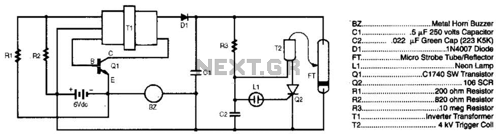
The burglar chaser is an effective accessory for any alarm system. It produces intense flashes of white light and generates a loud, irritating sound using a metal horn buzzer. Transformer T1 is connected to Q1, R1, and R2 to...

This circuit illustrates the NE555 timer used in a light-sensitive alarm sensor circuit diagram. Features include the ability to detect a sudden shadow falling on the sensor. The NE555 timer is a versatile integrated circuit widely utilized in various timing,...
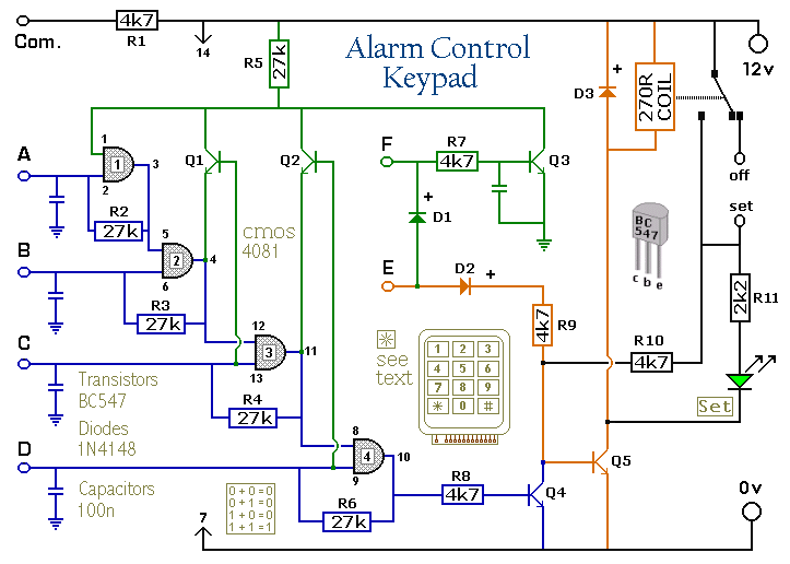
The Keypad must be the kind with a common terminal and a separate connection for each key. On a 12-key pad, look for 13 terminals. The matrix type with 7 terminals will NOT do. The Alarm is set by...
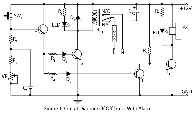
An off timer with an alarm is a straightforward project designed to indicate the end of a specified time period. The circuit utilizes four transistors. It includes a circuit diagram along with a parts list and a description of...

The IC 555 Light Alarm (Sun Up Alarm) is a circuit designed to emit a loud alarm at dawn, particularly beneficial for individuals who struggle to wake up even with a traditional alarm clock. The circuit can be modified. The...