
Ne7555 Timer For Light Sensitive Alarm Sensor

The NE555 timer is a versatile integrated circuit widely utilized in various timing, delay, pulse generation, and oscillator applications. In this specific configuration, the NE555 timer operates as a monostable multivibrator, which triggers an alarm when a light interruption is detected.
The circuit typically consists of a light-dependent resistor (LDR) that serves as the primary sensor. The LDR changes its resistance based on the intensity of the ambient light. When a sudden shadow or a decrease in light intensity occurs, the resistance of the LDR increases, causing a voltage drop across it. This change is detected by the NE555 timer, which is configured to respond to the threshold voltage at its trigger pin.
The circuit may include a resistor-capacitor (RC) network connected to the NE555 timer, which determines the timing duration of the alarm. The output from the timer can be connected to a relay or a transistor to activate an alarm or any other output device, such as a buzzer or LED indicator.
Power supply considerations for the circuit are essential, as the NE555 timer typically operates within a voltage range of 4.5V to 15V. Proper decoupling capacitors should be placed near the power supply pins of the IC to ensure stable operation.
Overall, this light-sensitive alarm sensor circuit utilizing the NE555 timer is an effective solution for applications requiring automatic detection of light changes, providing an audible or visual alert in response to sudden shadows or light interruptions.This circuit shows about Ne7555 Timer For Light Sensitive Alarm Sensor Circuit Diagram. Features: detects a sudden shadow falling on the .. 🔗 External reference
Related Circuits
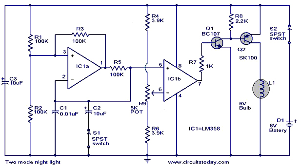
The operation and circuit diagram of a two-mode night light circuit are provided below. The two-mode night light circuit is designed to operate in two distinct lighting modes, typically offering a choice between a standard brightness setting and a dimmer,...

This simple Christmas LED lights decoration circuit allows for the creation of an 18 LED flasher to adorn a Christmas tree. The circuit incorporates white, blue, and red LEDs that flash in a festive pattern. The circuit is designed to...

This low-cost burglar alarm utilizes a 12V strobe light and a truck reversing horn as the visible and audible outputs, respectively, while the alarm system operates on a 12V power supply. The burglar alarm circuit is designed to provide an...

The following circuit illustrates a Slave Flash Light Control Circuit Diagram. Features include a 68mH inductor that provides an automatic trigger for the secondary flash light. The Slave Flash Light Control Circuit is designed to manage the operation of a...

This is a programmable clock timer circuit that uses individual LEDs to indicate hours and minutes. 12 LEDs can be arranged in a circle to represent the 12 hours of a clock face and an additional 12 LEDs can...

A simple voltage-controlled oscillator (VCO), coupled to instrumentation by an optoisolator, allows for the measurement of high voltages. The component values are suitable for a 0 to 600 V input range, with power dissipation in resistors RI and R2...