
Latching Continuity Tester

A latching continuity tester is a specialized electronic device designed to verify the integrity of electrical connections and circuits. It operates by sending a low-voltage signal through the component under test and determining whether the signal is able to pass through without interruption. This tool is particularly useful in diagnosing faults in cables, printed circuit boards (PCBs), switches, motors, plugs, and jacks.
The device typically includes an LED indicator that illuminates when continuity is detected, providing a clear visual signal to the user. The latching feature allows the tester to maintain its state, indicating continuity even after the test leads have been removed from the circuit. This is especially beneficial for troubleshooting, as it allows the technician to inspect the circuit without needing to hold the tester in place.
In terms of circuit design, a latching continuity tester may consist of a power source, often a battery, a resistor to limit current, a transistor or relay for switching, and an LED for indication. The power source energizes the circuit when the test leads are connected, while the resistor ensures that the current remains within safe limits to prevent damage to sensitive components. The transistor or relay acts as a switch, latching the circuit in the "on" state when continuity is detected, and the LED provides immediate feedback.
This device is indispensable in various applications, including electronics repair, maintenance, and assembly, ensuring that connections are secure and functional before proceeding with further work. Its compact design and straightforward operation make it a valuable tool for any technician or engineer involved in electronic testing and troubleshooting.Latching Continuity Tester. Source: Eldon L. Knight, Tony van Roon A continuity tester is a must on every service bench for testing cables, pcboards, switches, motors, plugs, jacks,. 🔗 External reference
Related Circuits
The continuity tester is a useful accessory to an ohmmeter. The unit or component whose continuity is to be checked is connected between terminals E1 and E2. A continuity tester is an essential tool in electronics for verifying the integrity...
The meter features a single scale ranging from 0 to 150, which is also utilized for measurements of 0 to 75 and 0 to 30. This limitation has led users to rely on calculators. A new meter scale has...
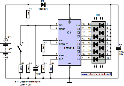
This circuit utilizes the widely available LM3914 integrated circuit (IC). The LM3914 is straightforward to operate, does not require external voltage regulators due to its built-in voltage regulation, and can be powered from nearly any voltage source. This makes...
Camping today often requires various electronic devices for daily activities and entertainment. Typically, a charged lead-acid battery and a power inverter are utilized to ensure a well-organized trip, allowing family members to enjoy their electronic equipment. It is essential...
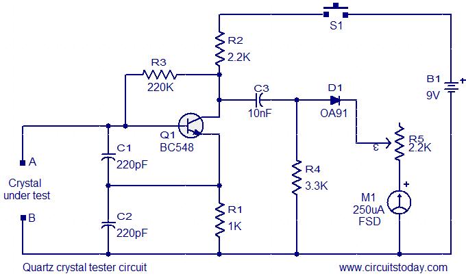
This is a straightforward and cost-effective circuit designed for testing quartz crystals. A Colpitts oscillator is employed using transistor T1. When the crystal is connected between terminals A and B, the circuit generates high-frequency oscillations. These oscillations will only...
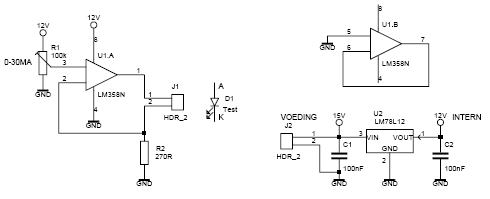
This led tester uses a power switched op-amp. The control range is about 0-30mA. Thus, all test and standard LEDs, the voltage across the LED to read. The power supply is an example lab power supply at least 15V,...