
Multiple Continuity Tester

A continuity tester is an essential tool in electronics for verifying the integrity of electrical connections. It operates by applying a small voltage across the terminals E1 and E2, with the component or circuit segment under test connected in between. If the connection is intact, current flows through the circuit, indicating continuity, often signaled by an audible beep or a visual indicator such as an LED light.
The design of a continuity tester typically includes a power source, often a battery, which provides the necessary voltage for testing. The circuit includes a resistor to limit the current and protect sensitive components. Additionally, an indicator circuit, which may consist of an LED and a current-limiting resistor, is employed to visually confirm the presence of continuity.
In practical applications, the continuity tester can be used to check for open circuits, verify connections in wiring, and troubleshoot faults in electronic devices. It is particularly useful in ensuring that all components in a circuit are properly connected before powering the system. The simplicity and effectiveness of a continuity tester make it a vital instrument for both professional technicians and hobbyists in the field of electronics.The continuity tester is a handy adjunct to an ohmmeter. The unit or component whose continuity is to be checked is connected between terminals E1 and E2.. 🔗 External reference
Related Circuits
This technique uses digital I/O pins to multiplex analog voltages into an analog input on the microcontroller. The method is most suitable for signals that do not need to be sampled frequently and it may be extended to accommodate...

Liquid crystal displays (LCDs) are available in various versions and sizes. The wide variety of features has led to some confusion regarding pin configurations. Consequently, even after extensive searching for a suitable screen, users often encounter difficulties in utilizing...
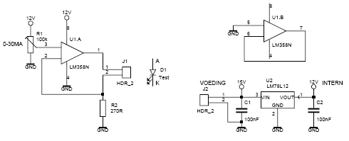
This led tester uses a power switched op-amp. The control range is about 0-30mA. Thus, all test and standard LEDs, the voltage across the LED to read. The power supply is an example lab power supply at least 15V,...
The concept for this crystal tester circuit originated from the necessity to evaluate a large quantity of oscillator crystals that were not in use within a hobby box. Testing each crystal individually without the proper equipment would have been...
Many blind and deaf-blind individuals utilize portable electronic devices to aid their daily activities; however, they face challenges when testing the batteries used in these devices. While talking voltmeters exist, there is no equivalent device suitable for deaf-blind users....
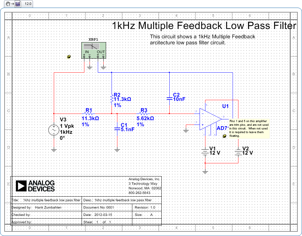
Pins 1 and 5 on this amplifier are trim pins and are not utilized in the circuit. When not in use, it is necessary to leave them floating. In electronic amplifier circuits, trim pins are often included for calibration or...