
200W Hybrid Audio Amplifier Circuit

To implement this circuit, two TDA2030 integrated circuits are utilized as the main amplification components. Each TDA2030 can deliver up to 14 watts of output power into a load of 4 ohms, but by connecting them in a configuration that includes additional power transistors, the overall output power can be significantly increased.
The circuit typically includes a power supply that provides the necessary voltage for the TDA2030s, usually around ±14 to ±20 volts, depending on the desired output power and load impedance. The output stage consists of complementary power transistors, such as NPN and PNP types, which are connected to the outputs of the TDA2030s. These transistors are responsible for driving the load with higher current, allowing the amplifier to deliver more power without distortion.
In the schematic, it is essential to include appropriate biasing resistors for the transistors to ensure they operate in their linear region. Additionally, capacitors may be used for coupling and decoupling purposes to stabilize the amplifier and prevent unwanted oscillations. Feedback resistors are also critical to maintain the desired gain and frequency response of the amplifier.
The input to the amplifier can be connected to audio sources, and it is advisable to include a volume control potentiometer to adjust the signal level entering the amplifier. Proper heat sinking for the TDA2030s and the power transistors is necessary to prevent overheating during operation, especially at higher power levels.
Overall, this configuration allows for a robust amplifier design that can drive larger speakers or provide greater sound output in various audio applications. The careful selection of component values and layout will ensure optimal performance and reliability of the final amplifier circuit.Connecting two TDA2030 thru cheap power transistors we can create a amplifier wich can deliver a higher power. With the components value from the schematic.. 🔗 External reference
Related Circuits
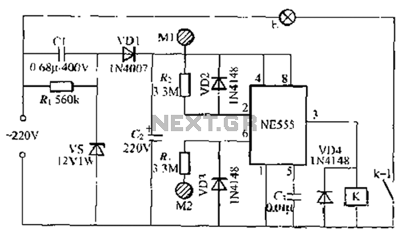
A use NF double touch lamp circuit based on a 55 base design, utilizing switches. It operates with 220V AC and includes a simple composition of a power-saving buck converter in conjunction with a half-bridge circuit. The circuit is...
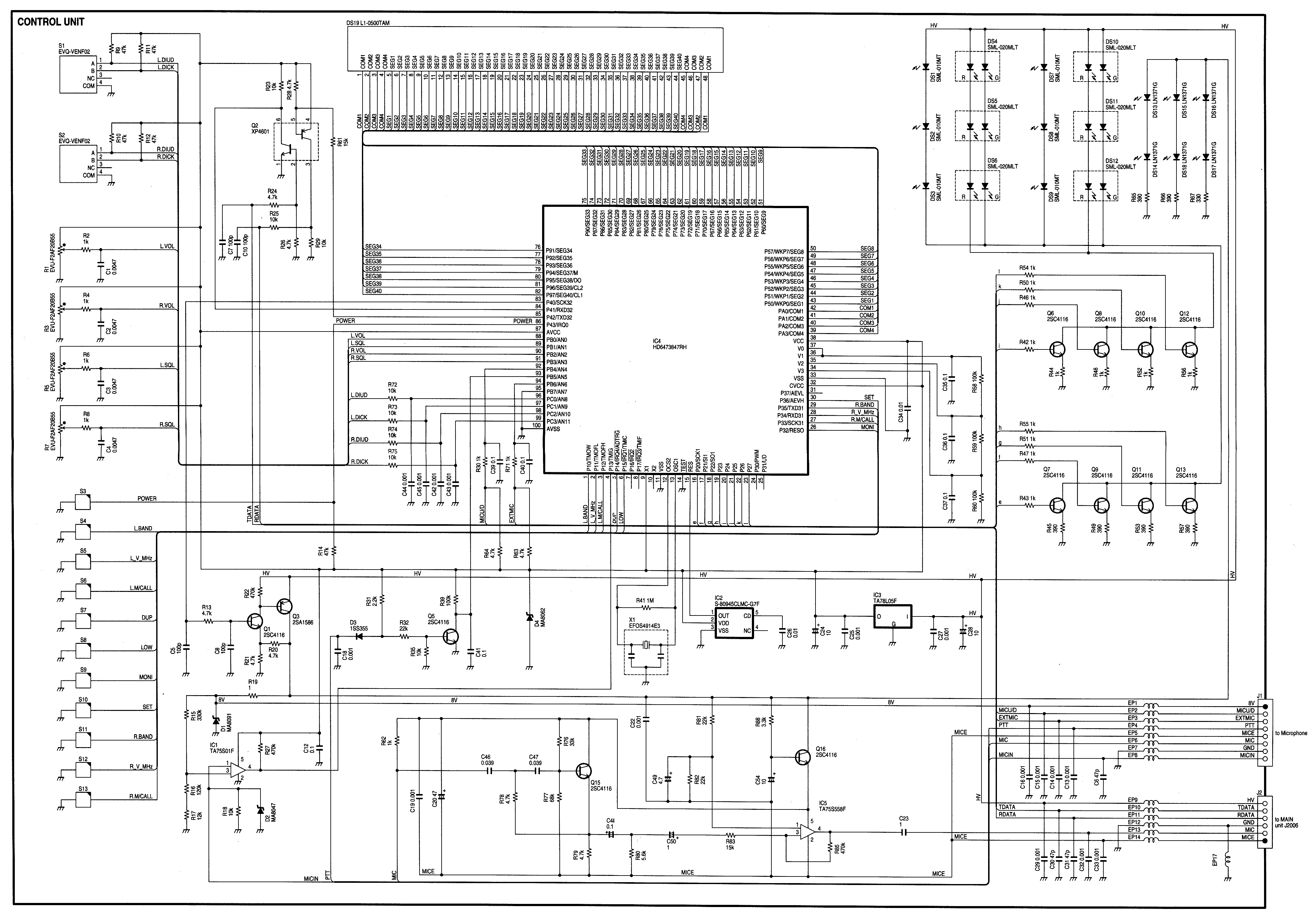
Radio Control Circuits PDF Manual Download. This document serves as a comprehensive guide to radio control circuits, intended for individuals seeking to understand the principles and applications of radio frequency (RF) technology in controlling various devices. The manual covers fundamental...
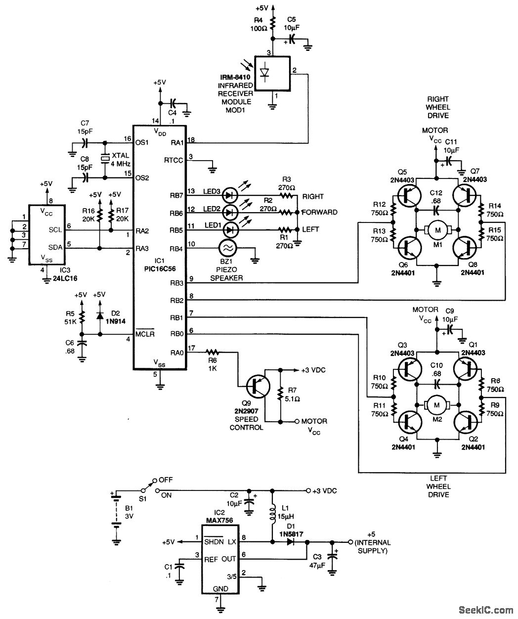
This article describes the Flip-Flop Flashers and Buzzers circuit utilizing the 2N4401 transistor. The content is straightforward and provides valuable insights. Components mentioned in this article can enhance the reader's understanding. For instance, the article includes information on where...
This easy electronic buzzer circuit is built based on a timer that operates to generate frequency. The IC timer NE555 is used as an astable multivibrator operating at approximately 1 kHz, producing a sound when powered on. The sound...
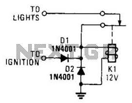
A relay and two diodes are all that is needed; the relay performs the job of a buzzer, so no annunciator is required. When the lights are left on while the ignition is off, the normally closed relay contacts...

This is a simple smoke alarm circuit using a timer IC, the NE555. The circuit operates by illuminating a Light Dependent Resistor (LDR) with a lamp. When smoke obscures the light from the lamp, the resistance of the LDR...