
LC meter 16x1 LCD Display

The LC meter circuit is designed to provide accurate measurements of inductance (L) and capacitance (C) over a wide range of values. The design typically incorporates a microcontroller or a dedicated integrated circuit (IC) that processes the measurement signals. The auto-ranging feature is implemented using a combination of analog switches and resistors, allowing the circuit to automatically select the appropriate range based on the detected signal level.
The operation of the LC meter relies on the resonant frequency formula, which is given by:
\[ f = \frac{1}{2\pi\sqrt{LC}} \]
Where:
- \( f \) is the resonant frequency in hertz (Hz),
- \( L \) is the inductance in henries (H),
- \( C \) is the capacitance in farads (F).
To measure inductance or capacitance, the circuit generates a known frequency signal which is then connected to the inductor or capacitor under test. The microcontroller measures the frequency shift caused by the component and calculates the value of L or C using the above formula.
The "Zero Out" switch is a critical feature for ensuring measurement accuracy. When activated, it allows the user to eliminate any parasitic capacitance or inductance that may affect the readings, thus enabling more precise measurements of the component in question.
The design may also include an LCD or LED display for easy reading of the measured values, and a power supply circuit that ensures stable operation of the meter. The overall layout of the circuit should be optimized for minimal noise and interference, which can be achieved through careful component placement and the use of shielding techniques if necessary.
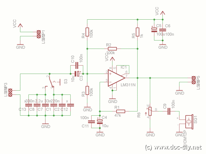
In summary, the described LC meter is a versatile tool for electronics enthusiasts and professionals alike, providing a compact and efficient means to measure inductance and capacitance with high accuracy.This is one of the most accurate and simplest LC inductance / capacitance Meters that one can find, yet one that you can easily build yourself. This LC Meter allows to measure incredibly small inductances starting from 10nH to 1000nH, 1uH to 1000uH, 1mH to 100mH and capacitance from 0.1pF up to 900nF.
LC Meter`s circuit uses an auto ranging system so that way you do not need to spend time selecting ranges manually. Another neat function is the "Zero Out" switch that will reset the initial inductance / capacitance, making sure that the final readings of the LC Meter are as accurate as possible.
To be able to determine the value of an unknown inductor / capacitor we can use the frequency formula given below. Note that there are three variables that we can work with; f, L and C (f represents a frequency, L inductance and C capacitance).
If we 🔗 External reference
Related Circuits
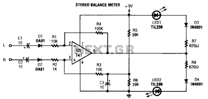
When the L and R signals are equal, no output is present from U1, and pin 6 is at a steady 4.5 V. Unbalanced audio causes the LEDs to vary in brightness, which indicates a difference that corresponds to...
This article explains the process of constructing a basic inductance meter. The printed circuit board (PCB) layout is provided. The construction of a simple inductance meter involves several key components and a well-designed PCB layout to ensure accurate measurements of...
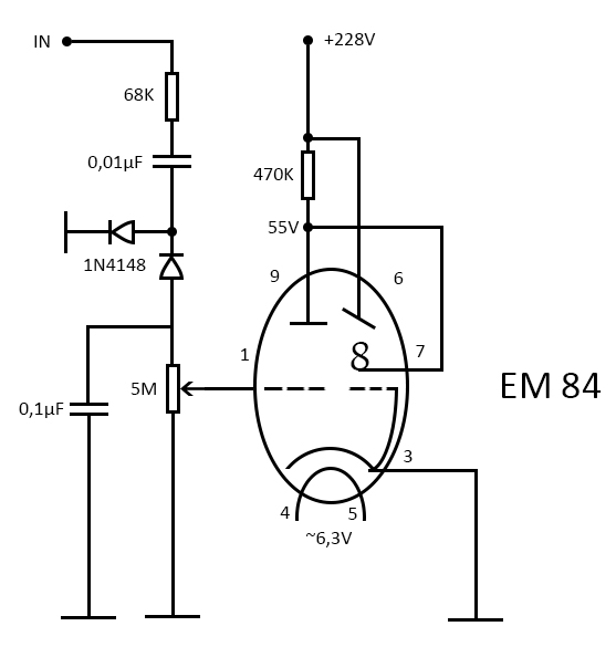
Among all existing tubes, the most captivating are the indicator tubes, which were invented in the 1930s. Their greenish shimmering light led to the term "Magic Eye." Magic Eye tubes are essentially small CRT derivatives, often incorporating a built-in...
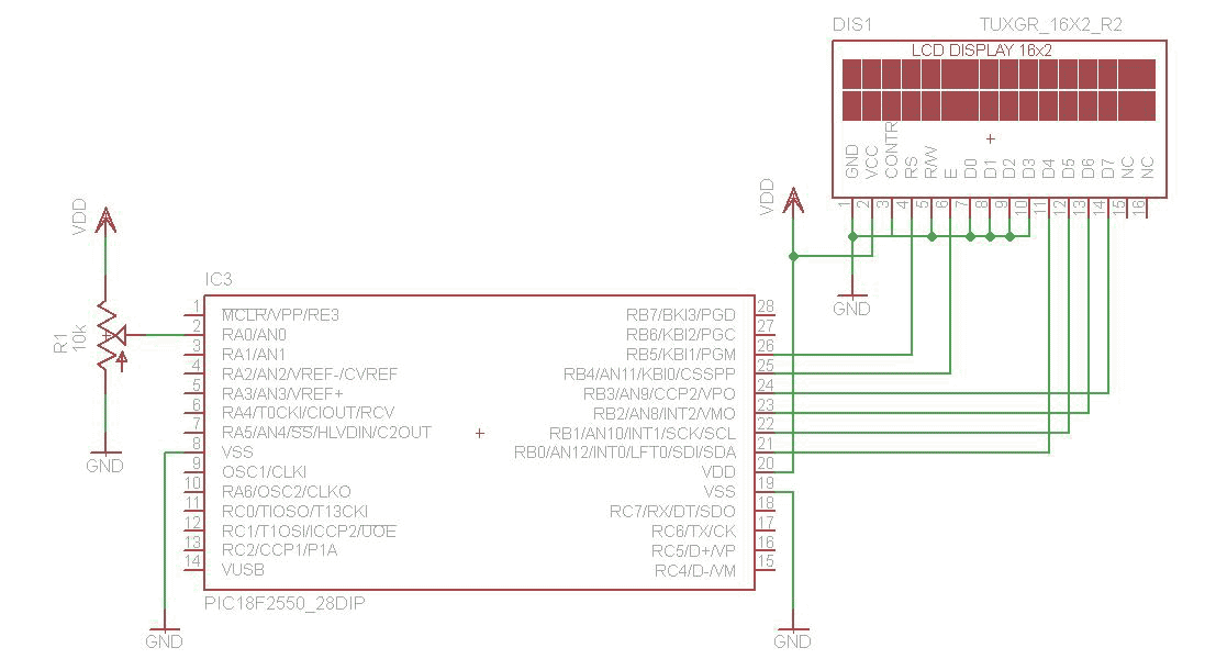
The analog to digital converter (ADC) is commonly required in most of the projects. Analog voltage measurement can be done using the ADC hardware built in together in a PIC. The picture below shows a simple setup for measuring...
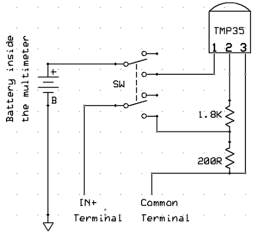
A digital multimeter is a highly versatile instrument that integrates multiple measurement functions within a single unit. Typically, a multimeter encompasses the functionalities of a variable-range ohmmeter, voltmeter, and ammeter, with some models also capable of testing diodes and...
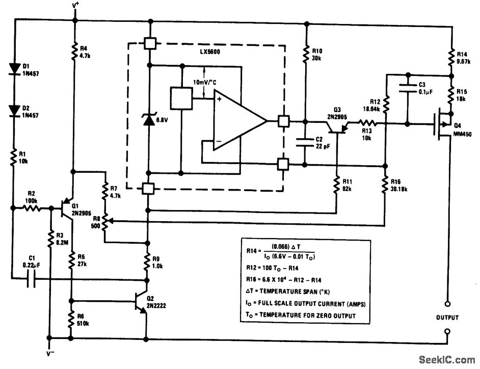
The output of this circuit is a current that is proportional to temperature, which can be utilized to drive a meter for direct readout. Alternatively, a resistor or operational amplifier can be employed to obtain a voltage output. The...