
simple inductance meter

The construction of a simple inductance meter involves several key components and a well-designed PCB layout to ensure accurate measurements of inductance. The primary components typically include an oscillator circuit, a microcontroller or timer, an analog-to-digital converter (ADC), and a display unit, such as a liquid crystal display (LCD) or light-emitting diode (LED) indicators.
The oscillator circuit generates a frequency that is dependent on the inductance of the coil being measured. This frequency can be derived using a 555 timer IC configured in astable mode, where the timing components (resistors and capacitors) are selected based on the expected range of inductance values. The output frequency of the oscillator is then fed into the microcontroller, which processes the frequency signal.
The microcontroller is programmed to calculate the inductance based on the frequency output from the oscillator. By using the formula for resonant frequency in an LC circuit, the inductance can be derived from the known capacitance and measured frequency. The ADC is utilized to convert the analog frequency signal into a digital format that the microcontroller can interpret.
The PCB layout should be designed to minimize noise and interference, which can affect measurement accuracy. Proper grounding techniques and the placement of components are crucial. The layout should also include mounting holes for securing the meter in a housing, as well as connections for the input terminals where the inductor will be connected.
Finally, the display unit presents the calculated inductance value to the user, allowing for easy reading and interpretation of results. This simple inductance meter can be a valuable tool for electronics enthusiasts and professionals alike, facilitating the measurement of inductors in various applications.This article describes how to build a simple inductance meter. The PCB layout is included.. 🔗 External reference
Related Circuits

The micro ampere meter presented here functions as a DC millivolt meter. It achieves full-scale deflection with a 0.1V input. The current to be measured flows through a known resistance R, and the voltage drop across this resistance is...
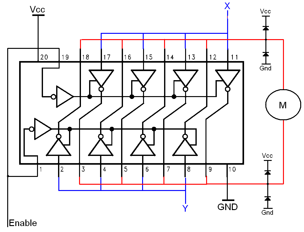
The H-bridge is a well-known and widely used circuit configuration for driving brushed DC motors. It enables straightforward control of motor direction, allowing for both forward and reverse operation. The H-bridge circuit consists of four switches, typically implemented using transistors...
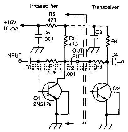
This simple, inexpensive, wideband RF amplifier provides 14 dB gain on two meters without the use of tuned circuits. The RF amplifier described operates within the two-meter band, which typically spans frequencies from 144 to 148 MHz. It is designed...
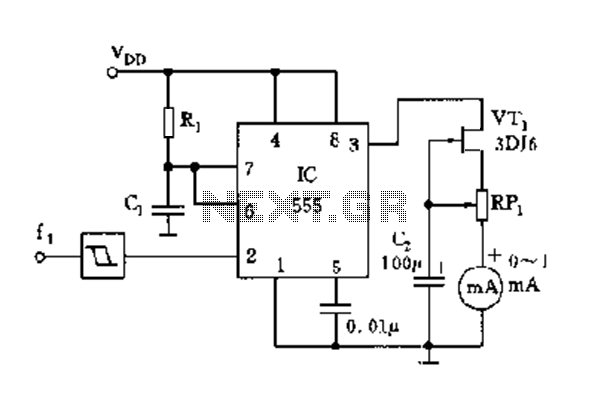
The circuit consists of a 555 timer along with components R1, C1, and other elements configured as a monostable delay circuit. The input square wave signal is shaped by a Schmitt trigger to meet the triggering requirements. The 555 timer...
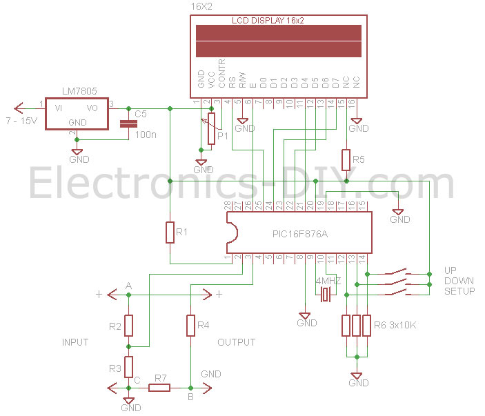
This voltmeter ammeter is designed to measure output voltage ranging from 0-70V to 0-500V with a resolution of 100mV and can measure current from 0-10A or more with a resolution of 10mA. It is an ideal addition to any...
An analog meter typically does not exhibit high impedance due to the absence of a buffer circuit within its design. By incorporating active buffering, the input impedance of this circuit can be significantly enhanced. The integration of an active buffer...